
Automatic sheet cutter for producing vacuum laminated glass

A technology of vacuum clips and cutting machines, which is applied in glass manufacturing equipment, glass cutting devices, manufacturing tools, etc., can solve the problems of reduced production efficiency, low work efficiency, and high maintenance costs, and achieve compact and reasonable structural design and improved cutting efficiency. Effective cutting efficiency and reasonable location design

Inactive Publication Date: 2017-07-07
嵊州市赫利玻璃制品有限公司
View PDF0 Cites 7 Cited by
  • Summary
  • Abstract
  • Description
  • Claims
  • Application Information

AI Technical Summary

Problems solved by technology

In the existing technology, manual or semi-automatic mechanical operations are generally used for glass cutting, which not only has certain requirements for the operator's technical proficiency, but also has low work efficiency, large product errors, and high labor costs.
[0003] There are also some enterprises that use automatic cutting machines to cut glass. However, the existing automatic cutting machines on the market are complicated to operate and inconvenient to use.
Moreover, when the existing automatic cutting machine cuts the glass, when one side of the glass is cut and the other side needs to be cut, the glass needs to be artificially rotated, which poses a greater safety hazard.
When there is a problem with the cutting blade of the automatic cutting machine, it is necessary to stop the work of the automatic cutting machine and replace and repair the cutting blade, which not only reduces the production efficiency, but also costs a lot of maintenance

Method used


Image

  • Automatic sheet cutter for producing vacuum laminated glass
  • Automatic sheet cutter for producing vacuum laminated glass
  • Automatic sheet cutter for producing vacuum laminated glass

Examples


Embodiment Construction

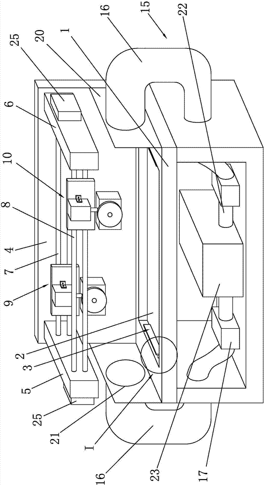
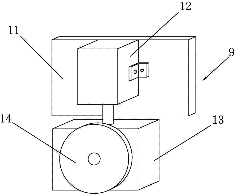
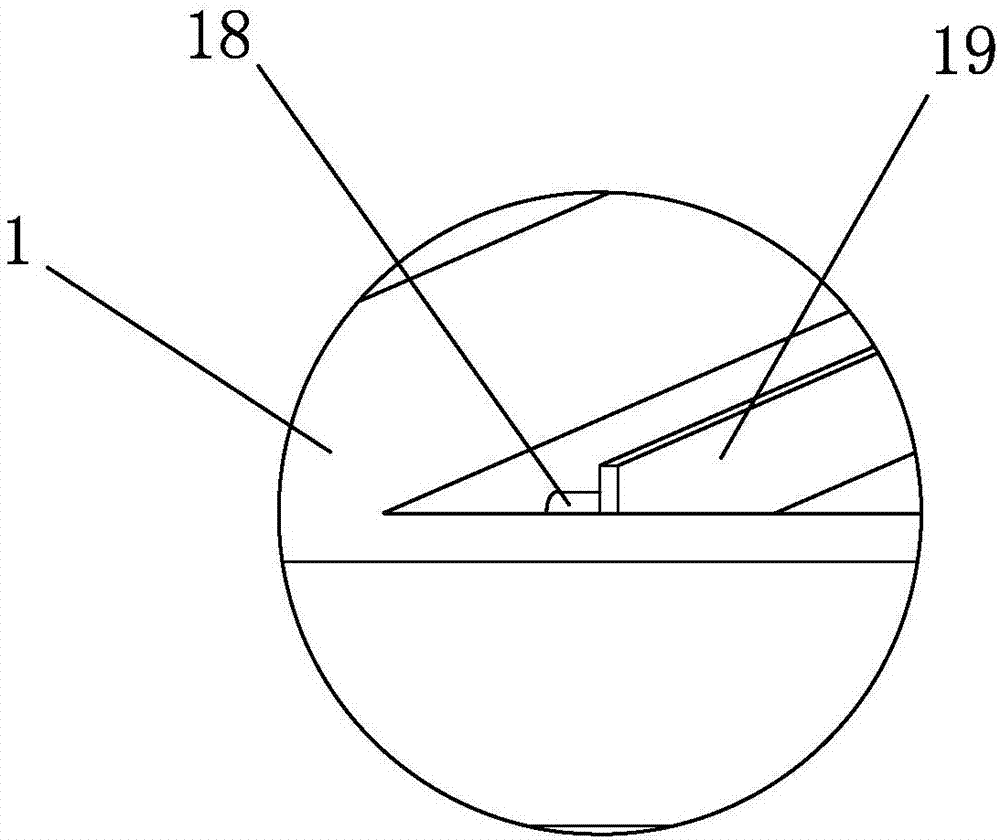
[0026] Such as Figure 1 to Figure 4 As shown, it is an automatic cutting machine for the production of vacuum laminated glass according to the present invention, which includes a cutting table 1, a cutting device and a dust collection device 15, and the left and right sides of the cutting table 1 are provided with shielding plates 20 to block The plate 20 is provided with a perforation 21, the elastic dust suction pipe 16 is connected with the shielding plate 20 through the perforation 21, the elastic dust suction pipe 16 matches the perforation 21, and the design of the shielding plate 20 can facilitate the installation and positioning of the elastic dust suction pipe 16 , the design of the perforation 21 can facilitate the limited connection between the elastic dust suction pipe 16 and the shielding plate 20, and the installation and operation are convenient.

[0027] The top surface of the cutting table 1 is provided with a placement groove 2, and the left and right sides ...


PUM


Abstract

The invention discloses an automatic cutting machine for the production of vacuum laminated glass, which comprises a cutting table, a cutting device and a dust collection device. The rear end face of the cutting table is provided with a mounting plate, the left side of the mounting plate is provided with a left positioning plate, the right side of the mounting plate is provided with a right positioning plate, and a first screw rod and a first screw rod are arranged between the left positioning plate and the right positioning plate. The second screw rod, the cutting device includes a first cutting assembly and a second cutting assembly, and the left and right sides of the cutting table are provided with dust suction devices, and the dust suction devices include elastic dust suction pipes and dust suction pumps. The invention is simple in structure, strong in practicability, and automatic in operation. The glass in the placement tank is positioned and clamped by the clamping device, and then the glass is cut simultaneously by the first cutting assembly and the second cutting assembly to increase the cutting rate. , At the same time, the glass shavings generated during cutting are absorbed by the vacuum device, and the overall structure design is more reasonable.

Description

technical field [0001] The invention relates to an automatic cutting machine for vacuum laminated glass production. Background technique [0002] In the production process of glass, it is necessary to cut large pieces of glass and cut them into small size glass pieces required by customers. In the existing technology, manual or semi-automatic mechanical operations are generally used for glass cutting, which not only requires a certain degree of technical proficiency of the operator, but also has low work efficiency, large product errors, and high labor costs. [0003] There are also some enterprises that use automatic cutting machines to cut glass, but the existing automatic cutting machines in the market are complicated to operate and inconvenient to use. Moreover, when the existing automatic cutting machine cuts the glass, when one side of the glass is cut and the other side needs to be cut, the glass needs to be manually rotated, which poses a greater safety hazard. Whe...

Claims


Application Information

Patent Timeline
IPC IPC(8): C03B33/023C03B33/03
CPCC03B33/023C03B33/03
Inventor 徐智根
Owner 嵊州市赫利玻璃制品有限公司
Learn More