Calibration method for light projection keyboard

A calibration method and light projection technology, which are applied in the input/output process of data processing, the input/output of user/computer interaction, and image data processing, etc., can solve the problems of low calibration efficiency, calibration error, and long time consumption.

Active Publication Date: 2017-07-07
哈尔滨拓博科技有限公司
View PDF6 Cites 8 Cited by
  • Summary
  • Abstract
  • Description
  • Claims
  • Application Information

AI Technical Summary

Problems solved by technology

[0004] The purpose of the present invention is to provide a method for calibrating an optical projection keyboard, so as to solve the problems of

Method used


Image

  • Calibration method for light projection keyboard
  • Calibration method for light projection keyboard
  • Calibration method for light projection keyboard

Examples


Embodiment 1

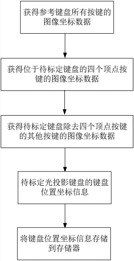
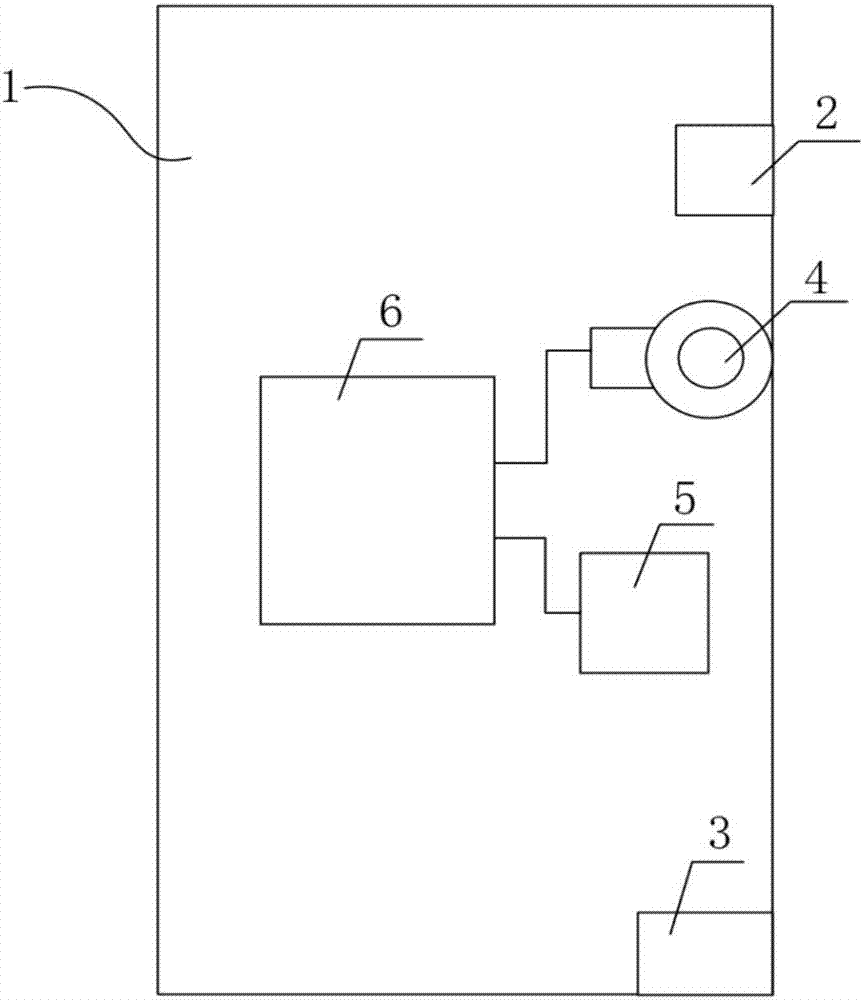
[0028] combine figure 1 and figure 2 The method for calibrating an optical projection keyboard according to an embodiment of the present invention is described. The optical projection keyboard 1 includes: a keyboard projection module 2, an infrared laser emitter 3, a device camera 4, a memory 5, and a processor 6; the keyboard projection Module 2 is used to project a virtual keyboard to the operation surface; the infrared laser emitter 3 is used to project infrared rays covering the virtual keyboard area; the device camera 4 is used to collect infrared images of the virtual keyboard area and The image is transmitted to the processor 6; the memory 5 is used to store the coordinate information of the keyboard position; the processor 6 is used to process the infrared image collected by the device camera 4 to obtain the coordinate information of the light spot reflected by the user's finger in the infrared image ; and compare the coordinate information with the keyboard position...

Embodiment 2

[0039] combine figure 1 and figure 2 The method for calibrating an optical projection keyboard according to an embodiment of the present invention is described. The optical projection keyboard 1 includes: a keyboard projection module 2, an infrared laser emitter 3, a device camera 4, a memory 5, and a processor 6; the keyboard projection Module 2 is used to project a virtual keyboard to the operation surface; the infrared laser emitter 3 is used to project infrared rays covering the virtual keyboard area; the device camera 4 is used to collect infrared images of the virtual keyboard area and The image is transmitted to the processor 6; the memory 5 is used to store the coordinate information of the keyboard position; the processor 6 is used to process the infrared image collected by the device camera 4 to obtain the coordinate information of the light spot reflected by the user's finger in the infrared image ; and compare the coordinate information with the keyboard position...


PUM

PropertyMeasurementUnit
Wavelengthaaaaaaaaaa

Abstract

The invention discloses a calibration method for a light projection keyboard. The method comprises the steps that 1, image coordinate data of all keys of a reference keyboard is obtained; 2, image coordinate data of four vertex keys of a to-be-calibrated keyword is obtained; 3, affine transformation is utilized to obtain image coordinate data of other keys, except the four vertex keys, of the to-be-calibrated keyword; 4, internal parameters, distortion and external parameters of a calibration camera and image coordinates of all the keys of the to-be-calibrated light projection keyword are utilized to obtain keyboard position coordinate information of all the keys of the to-be-calibrated light projection keyword; and 5, the keyboard position coordinate information is stored to a memory to complete calibration of the light projection keyword. The calibration method for the light projection keyboard is high in speed and efficiency and suitable for batch calibration, and the problems that manual determination of the image coordinate data of all the keys of the to-be-calibrated keyword is needed for manual calibration of the light projection keyboard, operation is repeated, and the amount of labor is large are solved.

Description

technical field [0001] The invention belongs to the technical field of optical projection keyboards, in particular to a calibration method for optical projection keyboards. Background technique [0002] The keyboard is one of the most commonly used input devices for electronic equipment, and it is widely used in computers, electronic instruments and various terminal equipment. The keyboard is the most commonly used and most important input device, through which English letters, numbers, punctuation marks, etc. can be input into the computer, so as to issue commands and input data to the computer. [0003] In order to solve the problems that the traditional physical keyboard is too large, difficult to carry and place, easy to absorb dust and difficult to clean, and easy to be damaged by excessive use, the equipment manufacturer has developed a virtual laser keyboard (Virtual LaserKeyboard). The virtual laser keyboard hardware mainly consists of 3 parts. Composition, that is,...

Claims


Application Information

Patent Timeline
IPC IPC(8): G06F3/02G06T7/80
CPCG06F3/0202
Inventor 李祝强杨佳锷侯文龙侯明鑫
Owner 哈尔滨拓博科技有限公司
Why Eureka
Try Eureka