
Light control circuit and electronic equipment

A technology for controlling circuits and electronic equipment, which is applied in the field of electronics and can solve the problems of inability to start up, troublesome, and inability to know the low-voltage charging state or non-low-voltage charging state of rechargeable batteries.

Active Publication Date: 2019-02-05
南京龙盾智能科技有限公司
View PDF8 Cites 0 Cited by
  • Summary
  • Abstract
  • Description
  • Claims
  • Application Information

AI Technical Summary

Problems solved by technology

[0004] However, the inventor has found that there is the following problem in the prior art: in the process of charging the existing electronic equipment, when the rechargeable battery is in a low-voltage charging state and a non-low-voltage charging state, the indicator light remains in a state (for example, the indicator light always on), the user cannot know whether the rechargeable battery is in a low-voltage charging state or a non-low-voltage charging state according to the state of the indicator light. cannot be turned on), but cannot be turned on successfully, the user may perform the startup operation several times, so that the rechargeable battery has changed from a low-voltage state to a non-low-voltage state when a certain operation is performed, and thus successfully turned on; it can be seen that the existing equipment can be turned on The process is more troublesome

Method used


Image

  • Light control circuit and electronic equipment
  • Light control circuit and electronic equipment
  • Light control circuit and electronic equipment

Examples


Embodiment Construction

[0017] In order to make the object, technical solution and advantages of the present invention clearer, various embodiments of the present invention will be described in detail below in conjunction with the accompanying drawings. However, those of ordinary skill in the art can understand that, in each implementation manner of the present invention, many technical details are provided for readers to better understand the present application. However, even without these technical details and various changes and modifications based on the following implementation modes, the technical solution claimed in this application can also be realized.

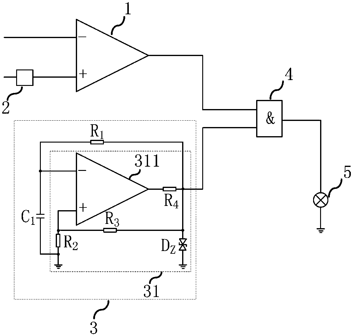
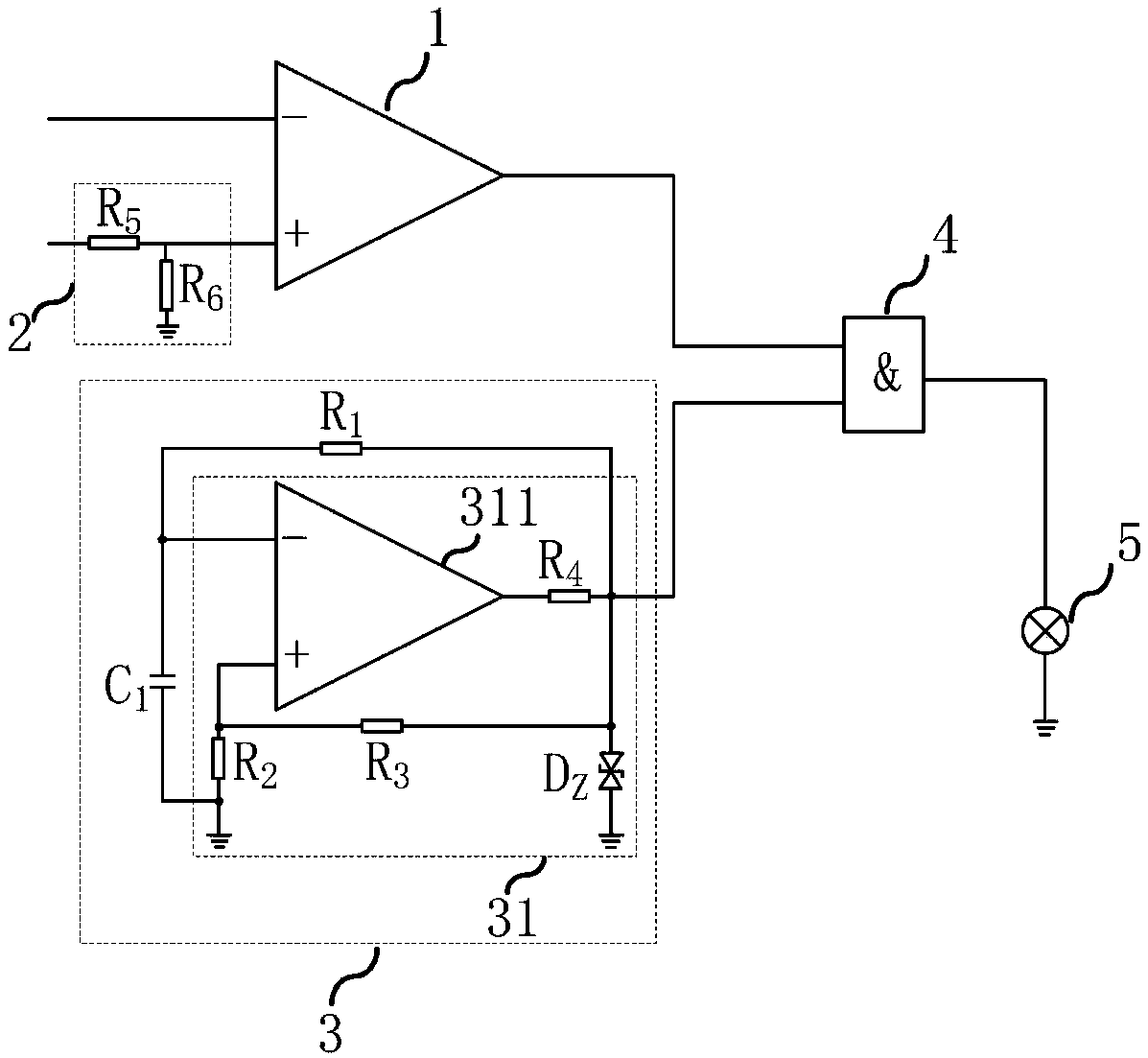
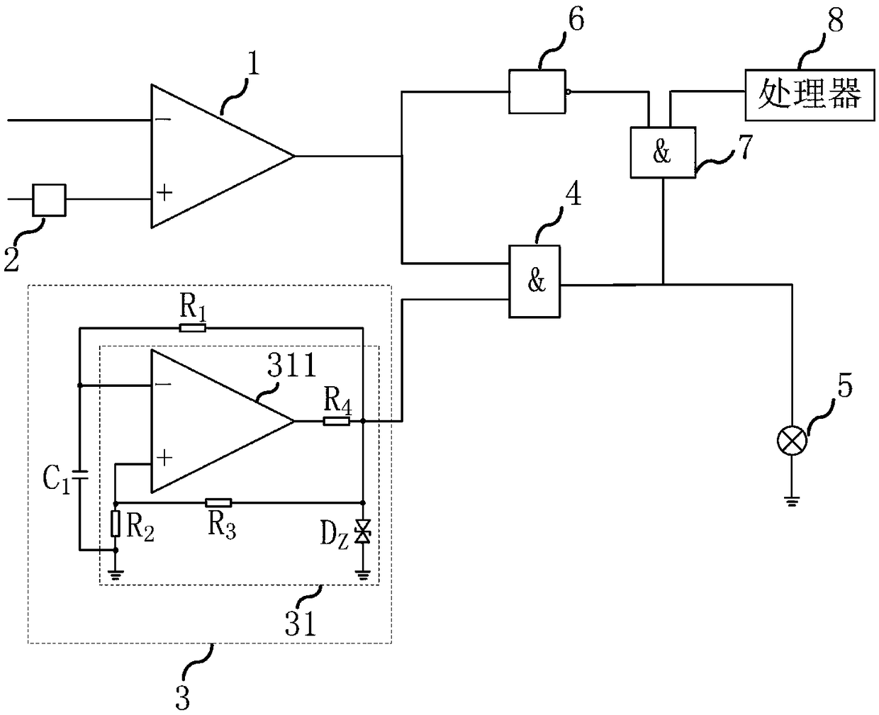
[0018] The first embodiment of the present invention relates to an indicator light control circuit, which is applied to an electronic device including a rechargeable battery and an indicator light, such as a mobile phone; figure 1 As shown, the indicator light control circuit of the embodiment of the present invention includes: a comparator...


PUM


Abstract

The embodiment of the invention relates to the field of electronic technology, and discloses an indicator light control circuit and electronic equipment. The indicator light control circuit of the embodiment of the present invention includes: a comparator, a voltage dividing unit, a pulse modulation unit and a first AND gate; The input terminal is used to connect the rechargeable battery and is used to receive the battery voltage signal; the output terminal of the comparator is connected to the first input terminal of the first AND gate, and is used to output the battery voltage signal and the divided charging voltage signal Comparing the signal; the pulse modulation unit is connected to the second input terminal of the first AND gate, and the output terminal of the first AND gate is connected to the indicator light; the embodiment of the present invention enables the indicator light to flash when the rechargeable battery is in a low-voltage charging state, thereby The user is reminded of the low-voltage charging state of the rechargeable battery, and the user is prevented from performing the power-on operation in the low-voltage charging state as much as possible, which provides convenience for the user to successfully power on.

Description

technical field [0001] The embodiments of the present invention relate to the field of electronic technology, in particular to an indicator light control circuit and electronic equipment. Background technique [0002] Mobile phones, tablet computers and other electronic devices are widely used in people's daily life, and the electronic devices are updated quickly. Some people may have multiple electronic devices; when the electronic devices are not used for a long time, the rechargeable batteries in the devices It may be in a low-voltage state, and it cannot be turned on immediately when it is used again, requiring the user to charge the rechargeable battery in the electronic device. [0003] Existing electronic equipment includes an indicator light and a rechargeable battery; when the user is charging the electronic equipment, when the rechargeable battery is in a low-voltage charging state, the indicator light will remain on to indicate that it is charging; when the rechar...

Claims


Application Information

Patent Timeline
Patent Type & Authority Patents(China)
IPC IPC(8): H05B33/08H05B44/00
CPCH05B45/00Y02B20/30
Inventor 杨志娟朱伟风
Owner 南京龙盾智能科技有限公司
Learn More