Bridge maintenance equipment

A technology for maintaining equipment and bridges. It is applied in lighting and heating equipment, clay preparation equipment, cement mixing equipment, etc. It can solve the problems of difficult filling of potholes, slow maintenance progress, low mixing efficiency, etc., and improve construction efficiency. The effect of maintenance speed, simple operation and simple structure

Active Publication Date: 2017-07-14
奉节县华东建筑工程有限责任公司
View PDF6 Cites 21 Cited by
  • Summary
  • Abstract
  • Description
  • Claims
  • Application Information

AI Technical Summary

Problems solved by technology

[0002] Mud is one of the most common raw materials in bridge pavement maintenance. It is mainly made by mixing cement and sand with water. It is mainly used to fill potholes after the bridge pavement is damaged. Traditionally, the mixing in the mud production process Generally, manual mixing is used. The mixing efficiency is low and the mixi

Method used


Image

  • Bridge maintenance equipment
  • Bridge maintenance equipment
  • Bridge maintenance equipment

Examples


Embodiment Construction

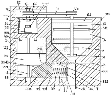
[0023] Such as Figure 1-Figure 5 As shown, a bridge maintenance equipment of the present invention includes a material box 1, a first sliding chamber 2 is provided inside the left side of the material box 1, and a first guide groove 23 is provided on the left inner wall of the first sliding chamber 2 The material box 1 on the right side of the first sliding cavity 2 is provided with a second sliding cavity 3 communicating with the first sliding cavity 2, and the material box 1 on the right side of the second sliding cavity 3 There is a discharge groove 4 extending up and down inside, and the top of the second sliding chamber 3 is provided with a closed groove 7 passing through the discharge groove 4 and extending to the right, and the top of the discharge groove 4 is provided with a tapered cavity 5 , the top of the tapered chamber 5 is provided with a feeding chamber 6, and the material box 1 above the first sliding chamber 2 is provided with a third sliding chamber 9, and t...


PUM


Abstract

The invention discloses bridge maintenance equipment comprising a material case. A first sliding cavity is formed in the interior of the left side of the material case. A first guiding groove is formed in the inner wall of the left side of the first sliding cavity. A second sliding cavity communicating with the first sliding cavity is formed in the interior, on the right side of the first sliding cavity, of the material case. A discharging groove extending up and down is formed in the interior, on the right side of the second sliding cavity, of the material case. A closing groove penetrating through the discharging groove and extending rightward is formed in the top of the second sliding cavity. A conic cavity is formed in the top of the discharging groove. A feeding cavity is formed in the top of the conic cavity. A third sliding cavity is formed in the interior, on the first sliding cavity, of the material case. Third guiding grooves are formed in the inner walls of the left and right sides of the third sliding cavity symmetrically. A spiral rod is arranged in the first sliding cavity. The bottom of the spiral rod is connected with a first driving machine. A lifting block is connected on the spiral rod in a threaded fit mode. The structure is simple, the design is reasonable, operation is easy, stirring and discharging work can be controlled automatically, the labor amount of workers is reduced, the construction maintenance speed is improved, meanwhile, a lighting function is achieved, the using cost is low, and the existing requirement is met.

Description

technical field [0001] The invention relates to the technical field of bridge equipment, in particular to bridge maintenance equipment. Background technique [0002] Mud is one of the most common raw materials in bridge pavement maintenance. It is mainly made by mixing cement and sand with water. It is mainly used to fill potholes after the bridge pavement is damaged. Traditionally, the mixing in the mud production process Generally, manual mixing is used. The mixing efficiency is low and the mixing is relatively uneven, which makes the maintenance progress slow. There are also many automatic mud mixing devices in the existing market, but their cost is high, the volume is too large, and it is inconvenient to move. The filling of many unevenly distributed potholes on the bridge pavement has major disadvantages and needs to be improved. Contents of the invention [0003] The technical problem to be solved by the present invention is to provide a bridge maintenance device, w...

Claims


Application Information

Patent Timeline
IPC IPC(8): B28C5/16B28C5/08F21V33/00F21Y115/10
CPCB28C5/0806B28C5/0818B28C5/0831B28C5/16F21V33/00
Inventor 沈菲菲
Owner 奉节县华东建筑工程有限责任公司
Why Eureka
Try Eureka