
New energy electric vehicle charging pile

A technology of charging piles and electric vehicles, which is applied in the direction of electric vehicle charging technology, electric vehicles, charging stations, etc., can solve the problems of reduced service life of connecting lines, inability to adjust, and low service life of connecting lines, so as to protect charging piles and prevent stumbling effect

Inactive Publication Date: 2017-07-14
TAICANG TAOXIN INFORMATION TECH CO LTD
View PDF0 Cites 9 Cited by
  • Summary
  • Abstract
  • Description
  • Claims
  • Application Information

AI Technical Summary

Problems solved by technology

The charging gun is inserted into the car socket, and its connecting wire is generally in contact with the ground, usually dragging the ground, being crushed and rubbed is a common occurrence, resulting in a reduced service life of the connecting wire, which cannot be conveniently adjusted according to the distance from the vehicle
[0003] In addition, when the tip of the charging gun and the socket of the electric vehicle are charging, the charging of the electric vehicle is generally only completed through the tip of the gun. The vibration of the gun head and the electric vehicle socket is caused. In order to overcome the impact, the charging gun head and the electric vehicle socket have to bear a large impact force, resulting in damage to the charging gun head. In a word, the connection of the charging gun in the prior art The service life of the line is generally not high

Method used


Image

  • New energy electric vehicle charging pile
  • New energy electric vehicle charging pile

Examples


Embodiment Construction

[0014] All features disclosed in this specification, or steps in all methods or processes disclosed, may be combined in any manner, except for mutually exclusive features and / or steps.

[0015] Any feature disclosed in this specification (including any appended claims, abstract and drawings), unless expressly stated otherwise, may be replaced by alternative features which are equivalent or serve a similar purpose. That is, unless expressly stated otherwise, each feature is one example only of a series of equivalent or similar features.

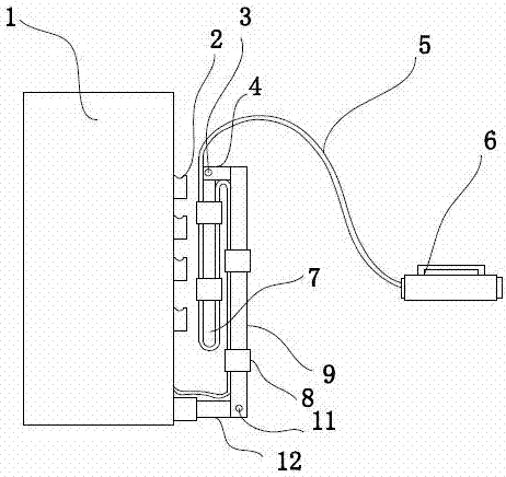
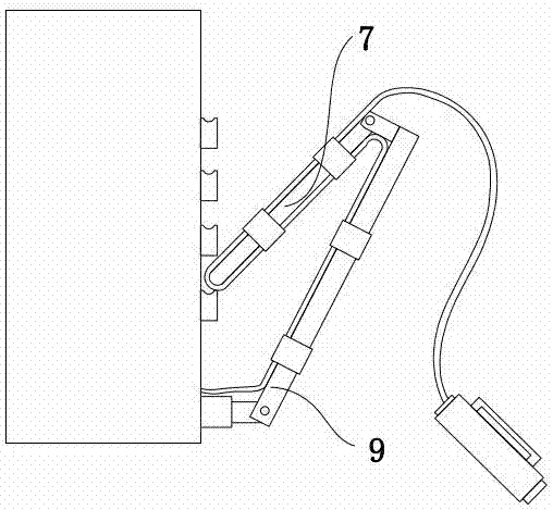
[0016] Such as figure 1 As shown, it includes a charging pile 1, a charging gun 6, and a connecting wire 5 for connecting the charging pile 1 and the charging gun 6. The bottom of the charging pile 1 is provided with a first connecting rod 12, and one end of the first connecting rod 12 is fixedly connected to The other end of the charging pile is rotatably connected to a first support rod 9 through the first rotating shaft 11, and the top of ...


PUM


Abstract

The invention discloses a new energy electric vehicle charging pile. The new energy electric vehicle charging pile comprises a charging pile body, a charging gun and a connection wire used for connecting the charging pile with the charging gun. A first connection rod is arranged at the bottom of the charging pile body, one end of the first connection rod is fixedly connected with the charging pile body, the other end of the first connection rod is rotationally connected with a first supporting rod through a first rotary shaft, the top of the first supporting rod is provided with a second connection rod perpendicular to the first supporting rod, the other end of the second connection rod is rotationally provided with a second supporting rod through a second rotary shaft, the first rotary shaft and the second rotary shaft are each provided with a torsional spring, and the first supporting rod and the second supporting rod are mutually parallel in the natural state of the torsional springs. The new energy electric vehicle charging pile can effectively ensure the situation that the connection wire does not fall to the ground during charging, prevent the connection wire from tripping and being ground, effectively prevent the situation that the connection wire is instantly pulled so that the charging gun and a vehicle have instant inserted link, and effectively protect the vehicle and the charging pile.

Description

technical field [0001] The invention relates to the field of new energy electric vehicles, in particular to a charging pile for new energy electric vehicles. Background technique [0002] New energy electric vehicles are powered by charging piles and charging guns. The charging gun is inserted into the car socket, and its connecting wire is generally in contact with the ground, usually dragging the ground, being crushed and rubbed is a common occurrence, resulting in a reduced service life of the connecting wire, which cannot be conveniently adjusted according to the distance from the vehicle . [0003] In addition, when the tip of the charging gun and the socket of the electric vehicle are charging, the charging of the electric vehicle is generally only completed through the tip of the gun. The vibration of the gun head and the electric vehicle socket is caused. In order to overcome the impact, the charging gun head and the electric vehicle socket have to bear a large imp...

Claims


Application Information

Patent Timeline
Patent Type & Authority Applications(China)
IPC IPC(8): B60L11/18
CPCB60L53/18B60L53/30B60L53/31Y02T10/70Y02T10/7072Y02T90/12Y02T90/14
Inventor 胡敏刚张宇
Owner TAICANG TAOXIN INFORMATION TECH CO LTD
Learn More