Curtain wall keel connection structure based on inner expansion groove

A connection structure and connection mechanism technology, applied in the direction of walls, building components, building structures, etc., can solve problems such as the influence of keel strength, a large number of connectors and screws, and damage, so as to improve the simplicity and delicacy of the appearance and improve the anti-bacteria Anti-corrosion ability, reducing the difficulty of installation

Active Publication Date: 2018-05-29
HUNAN GOLDWELL NEW MATERIALS TECH CO LTD
View PDF6 Cites 0 Cited by
  • Summary
  • Abstract
  • Description
  • Claims
  • Application Information

AI Technical Summary

Problems solved by technology

[0003] However, the existing curtain wall technology for post-installation of transverse keel is not mature enough, and there are many defects as follows:
[0004] 1. It is difficult to hide the connectors and screws between the keels, and most of the connectors and screws are exposed, which not only affects the installation of the curtain wall panels, but also makes the appearance of the curtain wall after installation not simple and delicate;
[0005] 2. The number of connectors and screws required for the connection between the keels is large, resulting in difficulty in disassembly and assembly and low efficiency, and it is also necessary to open a large number of fastening installation holes on the keel, which will affect the strength of the keel and reduce it. Rust resistance of the keel
[0006] 3. The force transmission between the keel and the connector is directly fastened by screws. There are problems such as difficulty in guaranteeing the connection strength, easy loosening and failure, and low safety. Moreover, the screws are all connected to the side wall of the keel, and the force balance is stable. And poor stability, the side wall of the tubular keel is also easily deformed and damaged, which requires high wall thickness of the keel, increasing the weight of the keel and the overall cost

Method used


Image

  • Curtain wall keel connection structure based on inner expansion groove
  • Curtain wall keel connection structure based on inner expansion groove
  • Curtain wall keel connection structure based on inner expansion groove

Examples


Embodiment 1

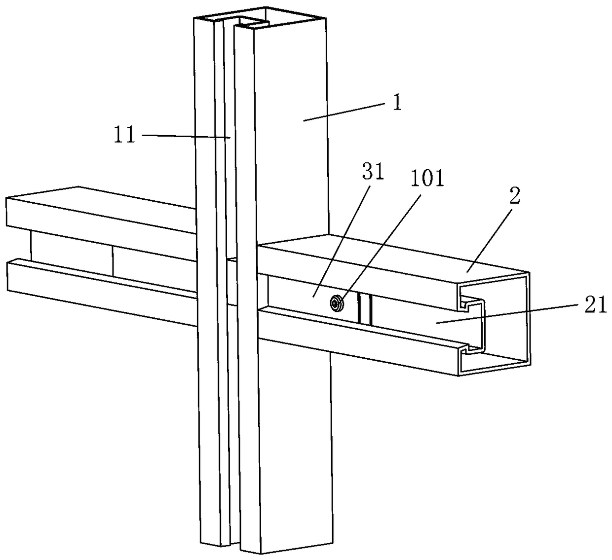
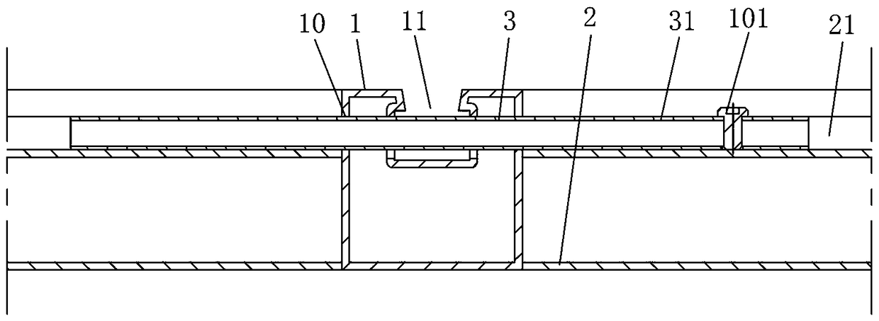
[0099] Such as Figure 1 to Figure 3 As shown, the curtain wall keel connection structure of this embodiment includes a vertical keel 1 and two horizontal keels 2 connected to both sides of the vertical keel 1 by connecting components. The vertical keel 1 is provided with a through installation hole 10, and the horizontal keel 2 has a horizontal The inner expansion groove 21, the transverse inner expansion groove 21 is opened on the front of the horizontal keel 2, and the connection assembly includes a sliding member 3 that can pass through the through mounting hole 10 and move along the lateral expansion groove 21, and the sliding member 3 penetrates Installed in the through mounting hole 10 and only slidably fits with the through mounting hole 10, the sliding member 3 has two lateral flared grooves 21 respectively located in the two horizontal keels 2 and only slides with the transverse flared groove 21 In the connecting portion 31, a first fastening component is provided betw...

Embodiment 2

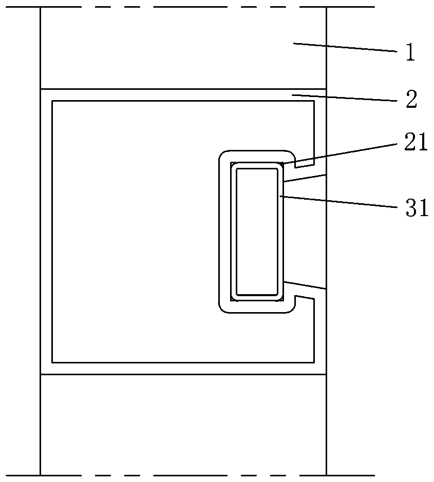
[0104] The curtain wall keel connection structure of this embodiment is basically the same as that of embodiment 1, the main difference is that, as Figure 4 As shown, in this embodiment, only the first fastening component is provided between the vertical keel 1 and the sliding member 3, and the vertical keel 1 does not have a vertical inward expansion groove 11, and the front of the vertical keel 1 is flat. The first fastening component is a second fastening screw 102. The second fastening screw 102 is installed on the vertical keel 1 and presses the sliding part 3, through the friction between the second fastening screw 102 and the sliding part 3 Prevent the sliding member 3 from sliding. The number of screws used in this embodiment is less, the assembly and disassembly are more convenient and quicker, and the surface of the horizontal keel 2 does not require holes, which will not affect the strength of the horizontal keel 2, and the horizontal keel 2 has better rust resistanc...

Embodiment 3

[0106] Such as Figure 5 to Figure 7 As shown, the curtain wall keel connection structure of this embodiment includes a vertical keel 1 and two horizontal keels 2 connected to both sides of the vertical keel 1 by connecting components. The vertical keel 1 is provided with a through installation hole 10, and the horizontal keel 2 has a horizontal The inner expansion groove 21, the connecting assembly includes a sliding member 3 that can pass through the through mounting hole 10 and move along the lateral expansion groove 21, the sliding member 3 is installed in the through mounting hole 10 and can be relative to the through mounting hole 10 rotates, the sliding member 3 has two connecting parts 31 respectively located in the lateral expansion grooves 21 of the two horizontal keels 2 and only slidingly fitted with the lateral expansion grooves 21. The vertical keel 1 and the sliding connection 3 pass The first fastening component is fixedly connected. The sliding member 3 is fixe...


PUM


Abstract

The invention discloses a curtain wall keel connection structure based on inner-expanded grooves. The structure comprises a vertical keel; one side or the two sides of the vertical keel is / are connected with transverse keels through connection assemblies; the transverse keels are provided with the transverse inner-expanded grooves; each connection assembly comprises a connector installed on the vertical keel; each connector is connected with a connection mechanism corresponding to one transverse keel; and part or all of each connection mechanism is installed in the corresponding transverse inner-expanded groove and matched with the transverse inner-expanded groove to at least limit all freedom degrees except movement of the corresponding transverse keel in the extending direction of the transverse inner-expanded groove. The curtain wall keel connection structure based on the inner-expanded grooves has the advantages of being high in connection strength, stability, reliability and installation efficiency, capable of advantageously improving the anti-rusting capacity and appearance conciseness and refinement of a curtain wall, and the like.

Description

Technical field [0001] The invention relates to the technical field of construction engineering, in particular to a curtain wall keel connection structure based on an internal expansion groove. Background technique [0002] At present, the horizontal and vertical keels of curtain walls on the market are mainly connected by splicing and welding. Among them, splicing is divided into two types: one is the sequential installation of sub-units, that is, the first vertical keel is installed first, and then the horizontal keel and the vertical keel are alternately installed on the side of the first vertical keel until the entire curtain wall is completed. The other is the post-installation method of horizontal keel, that is, first install all the vertical keels of the curtain wall according to the set interval size, and then install the horizontal keel between adjacent vertical keels. The disadvantage of the former installation method mentioned above is that once the keel needs to be r...

Claims


Application Information

Patent Timeline
Patent Type & Authority Patents(China)
IPC IPC(8): E04B2/96
CPCE04B2/965
Inventor 李杰谢斌泉其他发明人请求不公开姓名
Owner HUNAN GOLDWELL NEW MATERIALS TECH CO LTD
Why Eureka
Try Eureka