Twisting device for electrical conductors

An electrical conductor, twisting technology, applied in conductor/cable supply devices, cable/conductor manufacturing, circuits, etc., can solve problems such as high rejection, response delay, difficult error, etc., to achieve simple and easy adjustment, easy adjustment, and quality improvement Effect

Inactive Publication Date: 2017-07-14
SCHLEUNIGER HLDG
View PDF6 Cites 8 Cited by
  • Summary
  • Abstract
  • Description
  • Claims
  • Application Information

AI Technical Summary

Problems solved by technology

Even so, the force fluctuates by a predetermined value during the control process, and since the process is extremely dynamic, the response is bound to be delayed, making it very difficult to compensate for errors
It is almost impossible to maintain precise tension, and this can also lead to high rejection rates

Method used


Image

  • Twisting device for electrical conductors
  • Twisting device for electrical conductors
  • Twisting device for electrical conductors

Examples


Embodiment Construction

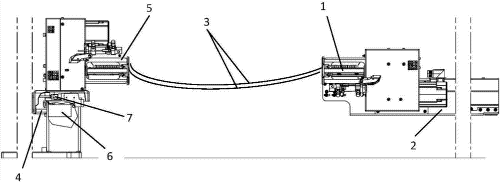
[0044] figure 1 The illustrated twisting device, which compensates for the shortening of the target length during the twisting process, has a twisting head 1 . The pair of conductors 3 to be twisted is held in position on the side opposite to the twisting head 1 by the second twisting head 5, wherein the two twisting heads 1, 5 can be rotated in opposite directions about a common axis of rotation . It is also possible to provide a non-rotating clamping device instead of the second twisting head 5 . As a variant, it is also possible to provide a non-rotating clamping device instead of the first twisting head 1 , in which case the second twisting head 5 is rotated. In principle, twisting of three or more conductors is also conceivable if the twisting heads 1 , 5 and the clamping device, in particular its clamping mechanism, are designed accordingly.

[0045] After the conductor pair 3 has been transferred to the twisting head 1 , 5 , the conductors are first arranged paralle...


PUM


Abstract

The invention relates to a twisting device for electrical conductors. The twisting device has at least one twisting head that rotates about an axis of rotation and a clamping device. The twisting head is movable in the direction of its axis of rotation toward the clamping device and is mounted on a first, motorised length compensation carriage, while the clamping device is mounted on a travel compensation carriage that is movable towards the length compensation carriage parallel to the axis of rotation of the twisting head. After the conductors have been cut to size and transferred to the twisting head and the clamping device, they are placed under tension. Then, the twisting head is activated to rotate about an axis of rotation parallel to the conductors while simultaneously moving towards the clamping device. Simultaneously, the clamping device is subjected to a force directed away from the twisting head and the travel/force profile for the clamping device is evaluated.

Description

technical field [0001] The invention relates to a twisting device for electrical conductors according to the preamble of claim 1 and a method thereof according to the preamble of claim 13 . Background technique [0002] WO2013068990A1 discloses a method for twisting electrical or optical conductors (such as wires, cables, cable bundles, waveguides, etc.) in a twisting device having two counter-rotatable twisting heads . The conductors are successively drawn into the twisting device between the twisting heads, and the distance between the twisting heads decreases as the twisting process progresses, preferably as a function of the number of revolutions of the twisting heads , to compensate for the overall shortening of the twisted conductor as the twisting continues. An advantageous variant provides for gradually increasing the rotational speed of the twisting head during the first phase of the twisting process and then gradually reducing the speed during the second phase of...

Claims


Application Information

Patent Timeline
Patent Type & Authority Applications(China)
IPC IPC(8): H01B13/02
CPCH01B13/0207H01B13/0271H01B13/0003H01B13/0036H01B13/0278
Inventor 乌维·凯尔罗兰德·卡普曼
Owner SCHLEUNIGER HLDG
Why Eureka
Try Eureka