
A counterweight transportation rail and a counterweight transportation method

A track and counterweight technology, applied in transportation and packaging, lifting equipment in mines, elevators, etc., to achieve the effect of improving safety and operating efficiency

Active Publication Date: 2017-07-18
MITSUBISHI ELECTRIC BUILDING TECH SERVICE CO LTD
View PDF7 Cites 0 Cited by
  • Summary
  • Abstract
  • Description
  • Claims
  • Application Information

AI Technical Summary

Problems solved by technology

In the structure described in Japanese Patent Application Laid-Open No. 11-349255, it is necessary to work hard to disassemble the counterweight in the hoistway and transport it to the upper landing entrance, so there is room for improvement in terms of safety and work efficiency.

Method used


Image

  • A counterweight transportation rail and a counterweight transportation method
  • A counterweight transportation rail and a counterweight transportation method
  • A counterweight transportation rail and a counterweight transportation method

Examples


Embodiment Construction

[0026] Embodiments of the present invention will be described below using the drawings. The shapes, numbers, materials, and the like described below are examples for explanation, and can be appropriately changed according to the specifications of the elevator to which the transport rail is applied. Hereinafter, the same reference numerals will be assigned to the same elements in all the drawings and will be described. In addition, in the description herein, the reference numerals described above are used as necessary.

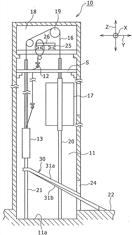
[0027] figure 1 It is a cross-sectional view showing a state in which the conveying rail 30 is installed in the elevator 10 to which the counterweight conveying rail of the embodiment is applied, and the lifting device 12 and the counterweight 13 are connected.

[0028] The elevator 10 has a counterweight 13 connected to a car 17 via a main rope 16 in a hoistway 11 . The main rope 16 is driven by a traction machine 19 arranged in a machine room 18 at the upp...


PUM


Abstract

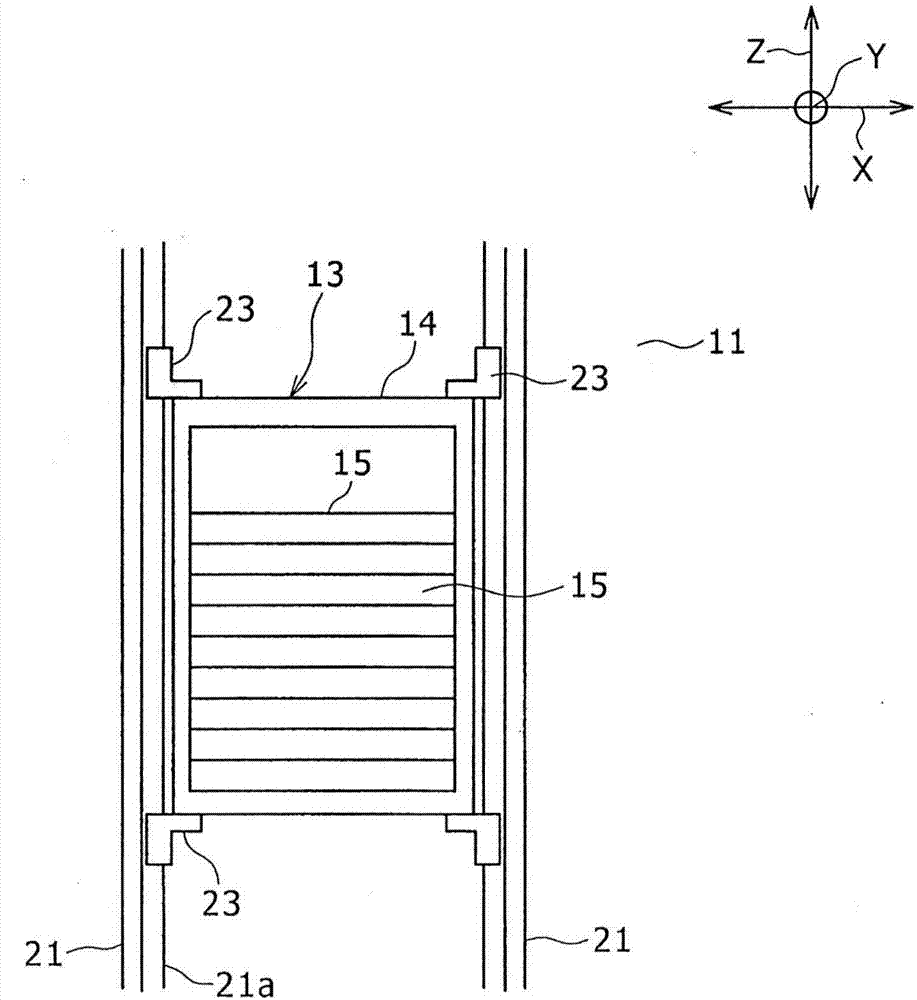
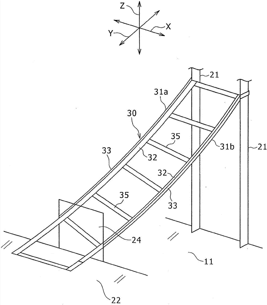
A counterweight transportation rail and a counterweight transportation method are provided; the transportation rail (30) is used to transport the counterweight between the hoistway (11) and the landing (22), which is the integration of the frame and the counterweight. The transportation rail (30) comprises two rail bodies (31a and 31b), and a plurality of columns (35), wherein the rail body comprises a curved long base plate (32) and a guide wall (33) connected with the upper side of the base plate; the columns allow the two rail bodies to connect in a plurality of positions in the length direction; In a state where one end portion in the longitudinal direction of the rail body is fixed to the counterweight and the other end portion of the rail body is disposed on the ground of the landing, the rail body is inclined in such a manner that the inclination angle of the base plate with respect to the horizontal direction is larger toward the lower side, thus allowing the interval between the two rail bodies decreases from the guiderail side to the layer station side in the left-right directions.

Description

technical field [0001] The present invention relates to a counterweight conveying track and a counterweight conveying method for conveying a counterweight in a hoistway and between landings in an elevator. The counterweight is formed by integrating a frame body and a counterweight. Background technique [0002] In the elevator, the car and the counterweight are connected by the main rope, and the car is moved up and down by the drive of the traction machine in the machine room. In recent years, the strength of the frame of the counterweight has been required to be increased by laws and regulations or the like. It is thus possible, if appropriate, to replace the existing counterweight with a new counterweight. [0003] Japanese Patent Laying-Open No. 11-349255 describes a method of replacing the counterweight of an elevator by lowering the counterweight to the bottom of the hoistway using a lifting device installed at the top of the hoistway and disassembling the counterweig...

Claims


Application Information

Patent Timeline
IPC IPC(8): B66B7/00B66B17/12
CPCB66B7/00B66B17/12
Inventor 竹内进
Owner MITSUBISHI ELECTRIC BUILDING TECH SERVICE CO LTD
Learn More