Display panel, display device and lens coordinate determining method

A display panel and coordinate determination technology, applied in optical components, instruments, optics, etc., can solve the problems of complex algorithms, irregular lens coordinate values, etc., to achieve the effect of simple algorithm, reduced complexity, and reduced amount of calculation data

Active Publication Date: 2017-07-18
SHANGHAI TIANMA MICRO ELECTRONICS CO LTD
View PDF4 Cites 0 Cited by
  • Summary
  • Abstract
  • Description
  • Claims
  • Application Information

AI Technical Summary

Problems solved by technology

[0005] However, the inventors found that the entire display panel is arranged with aperiodic lenses, which will lead to irregular coordinate values ​​of the lenses. When

Method used


Image

  • Display panel, display device and lens coordinate determining method
  • Display panel, display device and lens coordinate determining method
  • Display panel, display device and lens coordinate determining method

Examples


Embodiment Construction

[0057]The following will clearly and completely describe the technical solutions in the embodiments of the present invention with reference to the accompanying drawings in the embodiments of the present invention. Obviously, the described embodiments are only some of the embodiments of the present invention, not all of them. Based on the embodiments of the present invention, all other embodiments obtained by persons of ordinary skill in the art without making creative efforts belong to the protection scope of the present invention.

[0058] In order to solve the problem of complex algorithms caused by the non-periodic arrangement of lenses in the display panel provided by the prior art, the inventor proposes the following technical solutions:

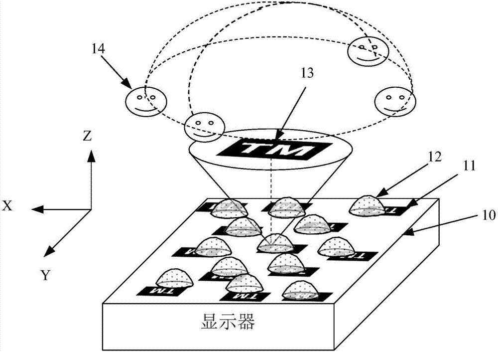
[0059] see figure 2 , figure 2 A schematic structural diagram of a display panel provided in this embodiment, wherein the display panel includes: a substrate 10 , an image block 11 and a lens 12 .

[0060] Specifically, the substrat...


PUM


Abstract

The invention provides a display panel, a display device and a lens coordinate determining method. According to the display panel, a substrate is divided into M*N display areas. Furthermore each display area is provided with at least two image blocks and at least two lenses. Each lens is in one-to-one correspondence with the image block. Furthermore the lens is arranged at the light outlet side of the image block. What needs to be explained is that the arrangement manners of the lenses in at least two display areas are different in all display areas which are included in the display panel, wherein the coordinates of the lenses in the display areas with the same lens arrangement manner are calculated according to the same algorithm. According to the display panel, the display device and the lens coordinate determining method provided by the invention, the display panel is divided into partially same display areas and partially different display areas or totally different display areas according to the lens arrangement mode, and individual calculation for the coordinate of the lens in each display area is required, thereby reducing complexity in performing error checking on the display panel.

Description

technical field [0001] The present invention relates to the field of display technology, and more specifically, to a display panel, a display device, and a method for determining lens coordinates. Background technique [0002] With the continuous development of science and technology, more and more electronic devices with display functions are used in people's daily life and work, which brings great convenience to people's daily life and work, and has become an indispensable important tool. [0003] Specifically, an electronic device with a display function mainly displays an image through a display, and generally, the display can be divided into a 2D display and a 3D display according to the display dimension of the image. Among them, the 3D display can display images more realistically, and has become a main development direction in the current display technology field. [0004] see figure 1 , figure 1 It is a structural schematic diagram of a 3D display in the prior a...

Claims


Application Information

Patent Timeline
IPC IPC(8): G02B27/22
CPCG02B30/27
Inventor 李嘉灵
Owner SHANGHAI TIANMA MICRO ELECTRONICS CO LTD
Why Eureka
Try Eureka