

Rehabilitation trainer for simultaneous movement of four limbs of hemiplegic patient
A sports rehabilitation and rehabilitation training technology, applied in passive exercise equipment, physical therapy and other directions, can solve the problems of low safety, poor patient rehabilitation effect, high price and other problems, so as to improve comfort, improve rehabilitation effect and comfort degree of effect
- Summary
- Abstract
- Description
- Claims
- Application Information
AI Technical Summary
Problems solved by technology
Method used
Image

Examples
Embodiment Construction
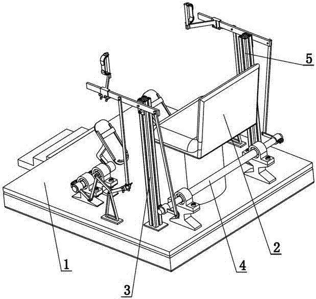
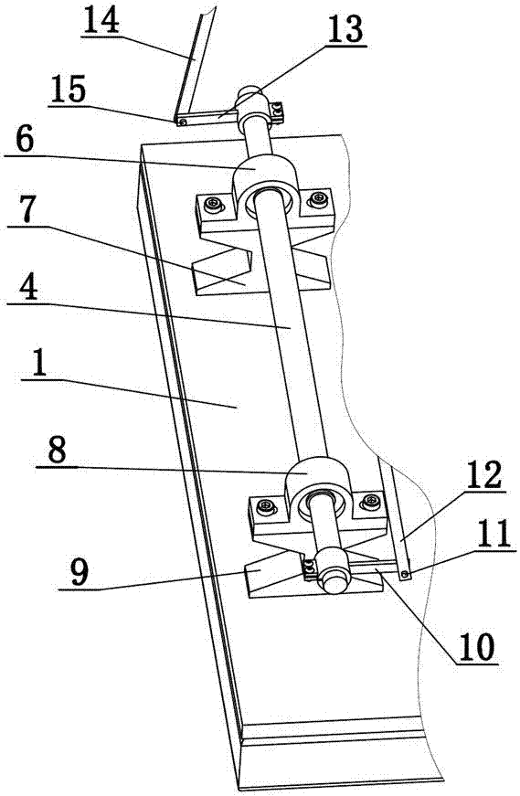
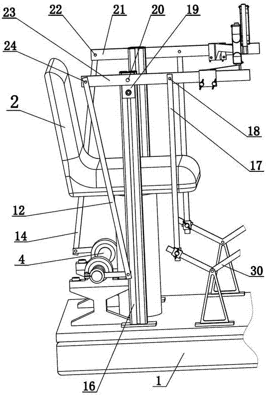
[0028] combine Figure 1~6 , a kind of hemiplegia patient's four limbs simultaneously exercise rehabilitation trainer of the present invention comprises base 1, seat 2, drive shaft 4, left swing bar 13, left connecting rod one 14, right swing link 10, right connecting rod one 12, left side Upper and lower limb rehabilitation training institution 3, right upper and lower limb rehabilitation training institution 5. The left and right directions are defined according to the orientation of a person sitting on a seat, so as to facilitate the description of this application. The seat 2 is fixed on the base 1, the left end of the transmission shaft 4 is fixedly connected to the front end of the left fork 13, and the left fork 13 is hingedly connected with the lower end of the left pin 15 and the left connecting rod 14. The right end of described power transmission shaft 4 fixes the rear end of right swing link 10, and the front end of right swing link 10 is hingedly connected with t...
PUM
 Abstract
Description
Claims
Application Information