
Punch pin drive device for press machine

A driving device and press technology, applied in the field of presses, can solve problems such as wasting electric energy, smashing molds, increasing machine height, etc., and achieves the effect of simple and reasonable structural design, simple structure, and lower product height

Inactive Publication Date: 2017-07-21
GUANGDONG METAL FORMING MACHINE WORKS
View PDF6 Cites 0 Cited by
  • Summary
  • Abstract
  • Description
  • Claims
  • Application Information

AI Technical Summary

Problems solved by technology

[0002] The deceleration mechanism of the existing large-scale presses is realized by the gear set, resulting in increased machine height, bulky, constant output power of the motor, wasting electric energy, and in case of a sudden power failure, the punch cannot be stopped due to the inertia of the motor down, will get out of control, smash the mold

Method used


Image

  • Punch pin drive device for press machine
  • Punch pin drive device for press machine

Examples


Embodiment Construction

[0010] The present invention will be further described below in conjunction with drawings and embodiments.

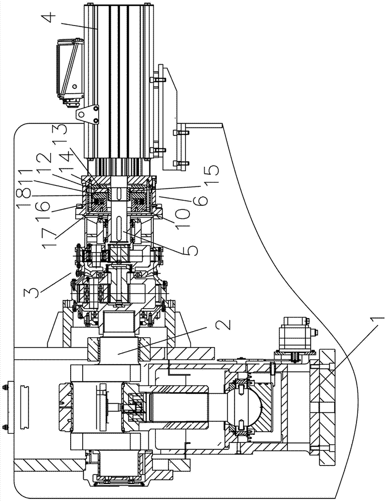
[0011] A punch driving device for a press, including a punch 1, a crank 2, a planetary reducer 3, and a servo motor 4, the crank 2 is connected to the planetary reducer 3, and the planetary reducer 3 and the servo motor 4 have an output shaft 5 Connected, the output shaft 5 of the servo motor is provided with a brake 6 .

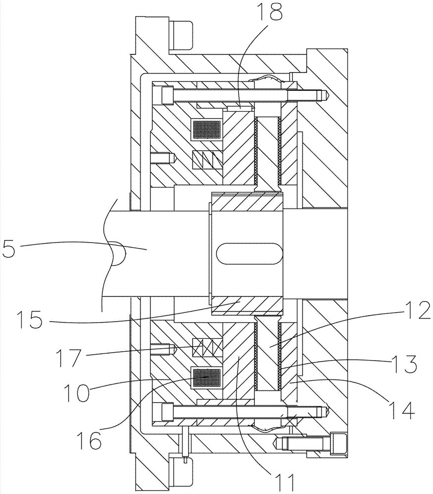
[0012] The brake 6 includes a stator 10, an armature 11, a rotor 12, a friction plate 13 and a flange 14. The rotor 12 is connected to the output shaft 5 of the servo motor through a splined bushing 15 and moves in unison. The stator 10 is provided with a coil 16 and a spring 17. The spring 17 is coaxial with the output shaft 5 of the servo motor. One end of the spring 17 is placed inside the stator 10, and the other end is placed on the armature 11. The outer ring of the armature 11 is provided with a flat key 18 to limit the armature to only move al...


PUM


Abstract

The invention discloses a press machine, and specifically relates to a punch pin drive device for a press machine. The punch pin drive device comprises a punch pin, a crank, a planetary speed reducer and a servo motor, wherein the crank is in transmission connection with the planetary speed reducer, the planetary speed reducer is connected with the output shaft of the servo motor, and a brake is arranged on the output shaft of the servo motor; and the brake comprises a stator, an armature, a rotor, a friction sheet and a flange, the rotor is connected and linked with the output shaft of the servo motor through a spline shaft sleeve, a coil and a spring are arranged in a stator body, the spring is coaxial with the output shaft of the servo motor, one end of the spring is jacked into the stator, the other end of the spring is jacked onto the armature, and a flat key is arranged on the outer ring of the armature and limits the armature to only axially move along the output shaft of the servo motor. The punch pin drive device disclosed by the invention is simple and reasonable in structural design; the planetary speed reducer is used in a replacement manner, so that the height of a product is lowered, and simple structure is achieved; and the servo motor is adopted, so that a power can be automatically adjusted according to output, and energy saving is realized.

Description

technical field [0001] The present invention relates to a press machine, in particular to a punch driving device of the press machine. Background technique [0002] The deceleration mechanism of the existing large-scale presses is realized by the gear set, resulting in increased machine height, bulky, constant output power of the motor, wasting electric energy, and in case of a sudden power failure, the punch cannot be stopped due to the inertia of the motor Come down, it will get out of control and smash the mold. Contents of the invention [0003] It is therefore an object of the present invention to provide a simple, safe and cost-effective punch drive for a press. [0004] The purpose of the present invention is achieved like this. [0005] A punch driving device for a press, including a punch and a crank, and also includes a planetary reducer and a servo motor. The crank is connected to the planetary reducer, and the planetary reducer is connected to the output shaf...

Claims


Application Information

Patent Timeline
Patent Type & Authority Applications(China)
IPC IPC(8): B30B1/26B30B15/10
CPCB30B1/26B30B15/10
Inventor 张贵成梁俊杰陆俞陈伟程何建定
Owner GUANGDONG METAL FORMING MACHINE WORKS
Learn More