
New energy automobile charging device

A technology for new energy vehicles and charging devices, applied in electric vehicle charging technology, charging stations, electric vehicles, etc., can solve the problems of loose plugging, interrupted charging, poor protection capability of charging heads, etc., to avoid looseness and increase safety. and stability effects

Active Publication Date: 2017-07-21
深圳龙电华鑫控股集团股份有限公司
View PDF3 Cites 37 Cited by
  • Summary
  • Abstract
  • Description
  • Claims
  • Application Information

AI Technical Summary

Problems solved by technology

[0002] The new energy vehicle industry is a new type of industry vigorously developed in my country. It has attracted people's attention for its many advantages such as energy saving and low exhaust emissions. New energy vehicles are vehicles with batteries as the energy storage power source. It uses batteries as energy storage power The battery provides electric energy to the motor, drives the motor to run, and thus drives the car to drive. The new energy car needs to be charged in time after driving. However, the charging head setting mode of the existing new energy car is relatively simple. Contact or shaking of the charging cable may cause the plug to loosen, which will lead to charging interruption and affect the normal charging use. Large or repeated mating may cause the pins to bend and deform, shortening the service life

Method used


Image

  • New energy automobile charging device
  • New energy automobile charging device
  • New energy automobile charging device

Examples


Embodiment Construction

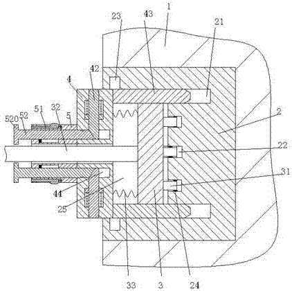
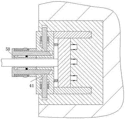
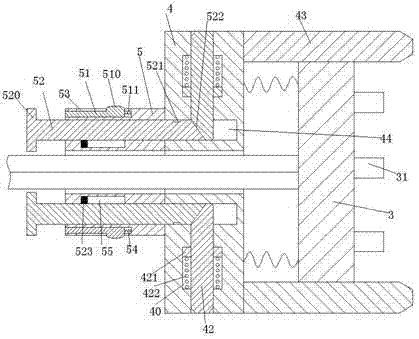
[0019] Combine below Figure 1-5 The present invention will be described in detail.

[0020] refer to Figure 1-5 , a new energy vehicle charging device according to an embodiment of the present invention, including a charging port 2 fixedly installed in a charging pile 1, a charging head 3 matched with the charging port 2, and a charging head 3 for protecting The bottom of the charging pile 1 is fixed with a base 101, the four corners of the bottom of the base 101 are respectively provided with corner posts 102, and the charging port 2 is provided with a sliding cavity 25 with a notch facing left, The right end wall of the sliding chamber 25 is provided with a fastening groove 22, and the conductive sheet 24 is arranged in the fastening groove 22, and the right end of the charging head 3 is fixedly provided with a plugging post 31 matching the fastening groove 22. , the left end of the charging head 3 is fixedly provided with a charging cable 32, the protective device inclu...


PUM


Abstract

Disclosed is a new energy automobile charging device. The new energy automobile charging device comprises a charging opening fixedly formed in a charging pile, a charging head matched with the charging opening and a load protecting device for protecting the charging head; a sliding cavity with a left notch is formed in the charging opening, a tight insertion groove is formed in the right end wall of the sliding cavity, an insertion column matched with the tight insertion groove is fixedly arranged at the right end of the charging head, the load protecting device comprises a runner which is in sliding fit with the sliding cavity and load protecting plates vertically and symmetrically installed at the right end of the runner, a control sleeve is fixedly arranged at the left end of the runner, guiding grooves matched with the load protecting plates are vertically and symmetrically arranged on the right end wall of the sliding cavity, symmetrically-arranged locking grooves are formed in the upper and lower end walls of the sliding cavity, first sliding grooves are vertically symmetrically formed in the runner in an extending mode, locking arms matched with the locking grooves are installed in the first sliding grooves in a sliding mode, the control sleeve is provided with a locking device for driving the locking arms and the locking grooves to be matched, and the control sleeve is provided with an opening device for relieving matching of the locking arms and the locking grooves.

Description

technical field [0001] The invention relates to the field of new energy vehicles, in particular to a charging device for new energy vehicles. Background technique [0002] The new energy vehicle industry is a new type of industry vigorously developed in my country. It has attracted people's attention for its many advantages such as energy saving and low exhaust emissions. New energy vehicles are vehicles with batteries as the energy storage power source. It uses batteries as energy storage power The battery provides electric energy to the motor, drives the motor to run, and thus drives the car to drive. The new energy car needs to be charged in time after driving. However, the charging head setting mode of the existing new energy car is relatively simple. Contact or shaking of the charging cable may cause the plug to loosen, which will lead to charging interruption and affect the normal charging use. Large or repeated mating may cause the pins to bend and deform, shortening th...

Claims


Application Information

Patent Timeline
IPC IPC(8): B60L11/18
CPCB60L53/16B60L53/30B60L53/31Y02T10/70Y02T10/7072Y02T90/12Y02T90/14
Inventor 吴敏俊
Owner 深圳龙电华鑫控股集团股份有限公司
Learn More