
Breaking device of cast-in-place concrete pile head and construction method thereof

A construction method and concrete technology, which is applied to sheet pile walls, foundation structure engineering, construction, etc., can solve the problems of large dust, high labor intensity, and large demolition workload during the demolition process, and achieve fast and efficient truncation and hoisting, and reduce The investment of manpower and material resources and the effect of eliminating hidden dangers of engineering safety

Pending Publication Date: 2017-07-21
CCCC SECOND HARBOR ENG
View PDF5 Cites 2 Cited by
  • Summary
  • Abstract
  • Description
  • Claims
  • Application Information

AI Technical Summary

Problems solved by technology

Since this method removes from the periphery of the pile head inward, on the one hand, there is a risk of damaging the main reinforcement during the removal process; , high labor intensity, slow construction speed, high dust and high risk during the demolition process, especially not suitable for the demolition operation of pile heads of large-diameter pile foundations, and large-diameter pile foundations belong to the current development trend of bridge pile foundations

Method used


Image

  • Breaking device of cast-in-place concrete pile head and construction method thereof
  • Breaking device of cast-in-place concrete pile head and construction method thereof
  • Breaking device of cast-in-place concrete pile head and construction method thereof

Examples


Embodiment Construction

[0025] The present invention will be further described in detail below in conjunction with the accompanying drawings and specific embodiments.

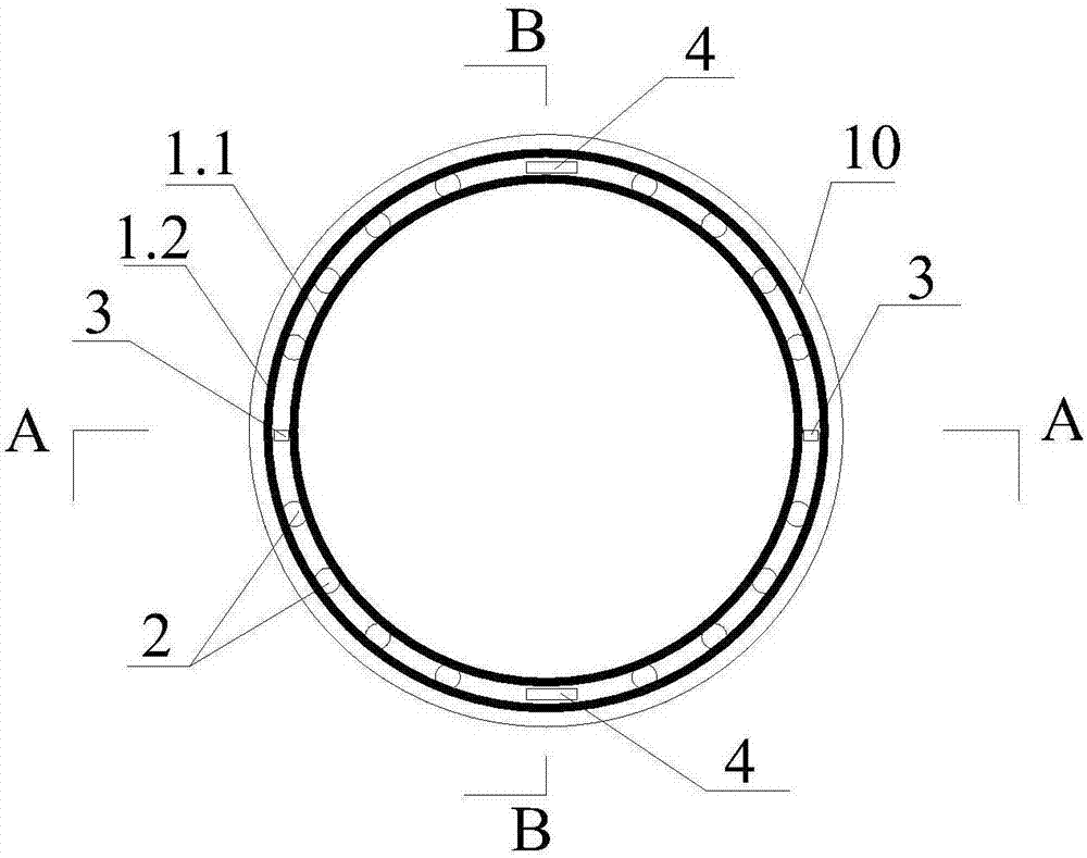
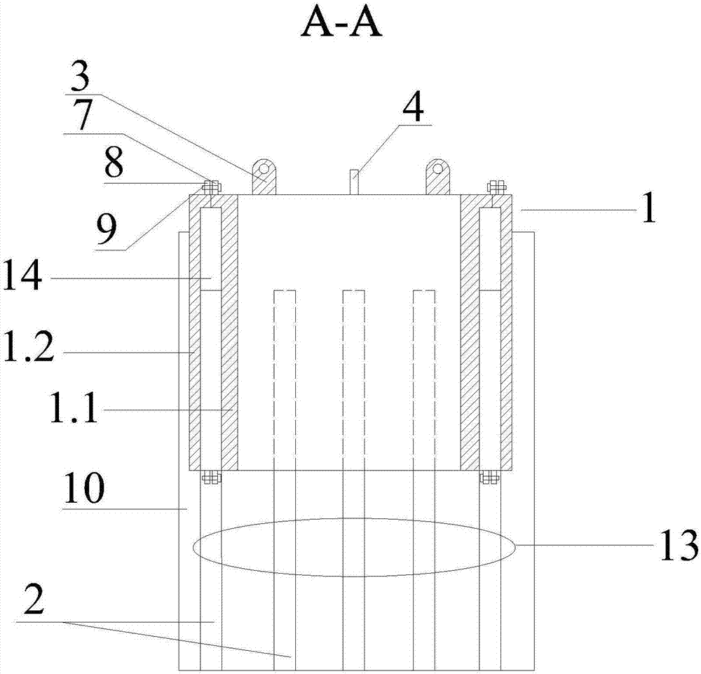
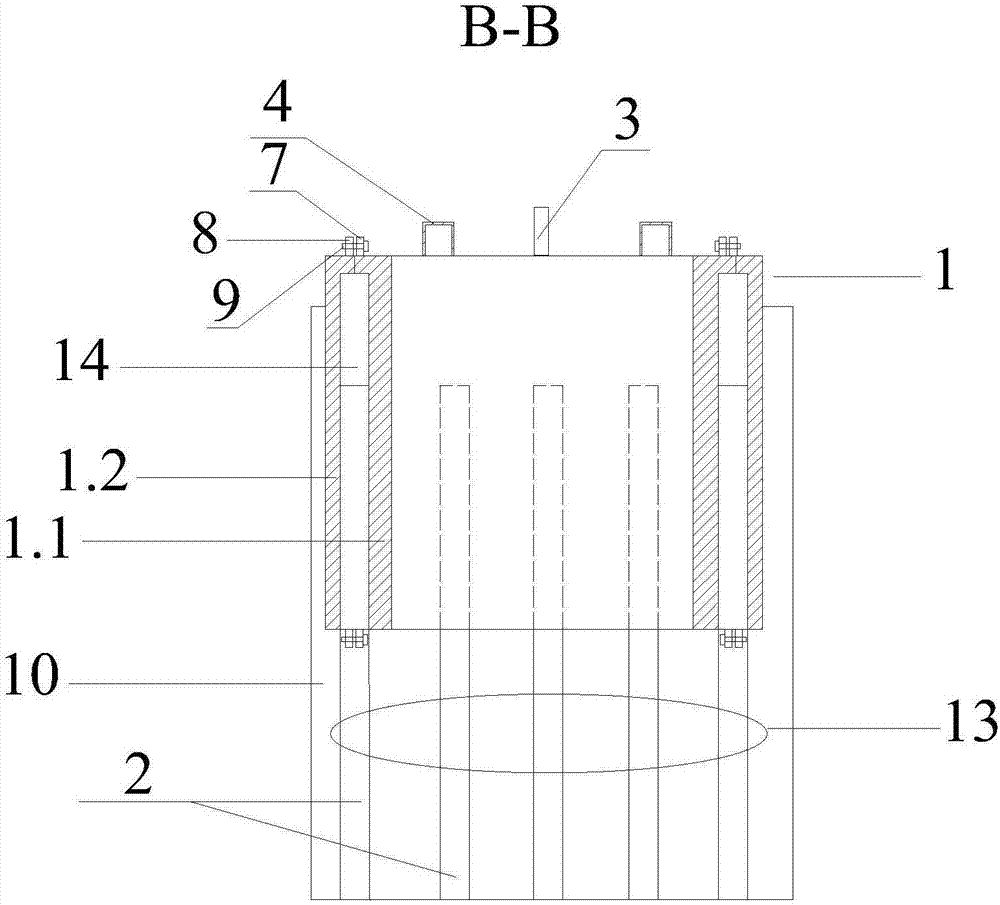
[0026] Such as figure 1 The demolition device for the pile head of the concrete pouring pile shown in —5 includes an annular main reinforcement positioning casing 1, and the main reinforcement positioning casing 1 includes two coaxial annular inner casings 1.1 and annular outer casing 1.2, and the annular inner casing The outer wall of 1.1 fits and fixes with the inner wall of the annular outer casing 1.2, and the main rib positioning groove 14 includes the first main rib positioning half-groove 5 opened on the outer wall of the annular inner casing 1.1 and corresponding to the first main rib positioning half-groove 5, opened in The second main rib on the inner wall of the annular outer casing 1.2 positions the half groove 6 . Two lifting lugs 3 that are symmetrical to the axis of the main reinforcement positioning casing 1 are fixed...


PUM


Abstract

The invention discloses a breaking device of a cast-in-place concrete pile head. The breaking device comprises an annular main rib positioning protection cylinder, a main rib positioning groove corresponding to a main rib is formed in the main rib positioning protection barrel, and the top of the main rib positioning protection cylinder is fixedly provided with lifting lug plates and steel bar penetrating supports which allow supporting steel bars of a steel bar cage to penetrate through and position the supporting steel bars of the steel bar cage; the main rib positioning protection barrel comprises an annular inner protective barrel and an annular outer protective barrel which are coaxial, and the outer wall of the annular inner protective barrel is attached and fixed to the inner wall of the annular outer protective barrel; and the main rib positioning groove comprises a first main rib positioning half-groove which is formed in the outer wall of the annular inner protective barrel, and a second main rib positioning half-groove which corresponds to the first main rib positioning half-groove and is formed in the inner wall of the annular outer protective barrel. According to the breaking device, the gripping force between the main rib and the pile head concrete is reduced, the risk of damaging the main rib is eliminated, meanwhile, the pile head becomes smaller and smaller and can be broken block by block, the performance requirements for hoisting equipment are reduced, the construction work efficiency is improved and the application range is expanded.

Description

technical field [0001] The invention relates to the technical field of civil engineering foundation construction, in particular to a device for removing a pile head of a concrete pouring pile and a construction method thereof. Background technique [0002] Concrete pouring piles are widely used in various foundation projects because of their reliable quality, mature construction technology, strong stratum adaptability and good bearing capacity. In the construction of cast-in-place piles, in order to ensure the quality of the concrete at the pile head and avoid the specification that the end of the pile foundation is mixed with laitance and mud, it is required that the poured concrete should exceed the set height of the pile head by 0.5-1.0m, and then Chisel off the protruding part (called the broken pile head). In order to chisel away the concrete beyond the pile head of the set cast-in-situ pile, manual chiseling or manual-assisted small-scale mechanical removal are genera...

Claims


Application Information

Patent Timeline
Patent Type & Authority Applications(China)
IPC IPC(8): E02D9/00
CPCE02D9/00
Inventor 罗洪成胡义新卢佩周舒刘宁波李送根王路李琴
Owner CCCC SECOND HARBOR ENG
Learn More