Sliding valve type plunger oil-well pump

A technology of oil well pump and plunger, which is applied in the field of slide valve type plunger oil well pump, which can solve the problems of high cost ratio of valve ball and valve seat, easy occurrence of air lock and sand stuck, and lax valve ball setting, etc., so as to reduce the processing cost cost, saving training and learning costs, and reducing operating costs

Active Publication Date: 2017-07-21
SHANDONG WEIMA PUMPS MFG
View PDF6 Cites 0 Cited by
  • Summary
  • Abstract
  • Description
  • Claims
  • Application Information

AI Technical Summary

Problems solved by technology

[0002] In the process of oilfield development, the plunger pump is one of the main lifting equipment. The traditional plunger pumps are equipped with fixed valves and floating valves. These valves are equipped with valve balls and valve seats. The disadvantages are: due to the influence of well conditions and water hammer effect, during the operation of the plunger pump, the valve seat is prone to leaking, the valve ball is not tightly set, etc., resulting in reduced pump efficiency or failure, and prone to occurrence of Air lock and sand stuck phenomenon; during the manufacturing process, the valve ball and seat account for a relatively high proportion of the cost

Method used


Image

  • Sliding valve type plunger oil-well pump
  • Sliding valve type plunger oil-well pump

Examples


Embodiment Construction

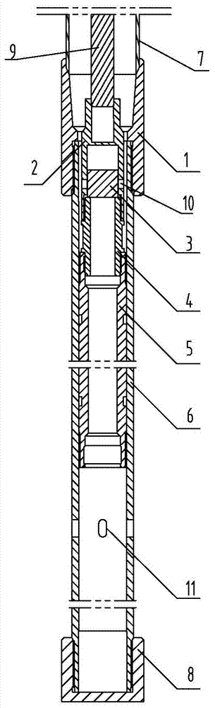
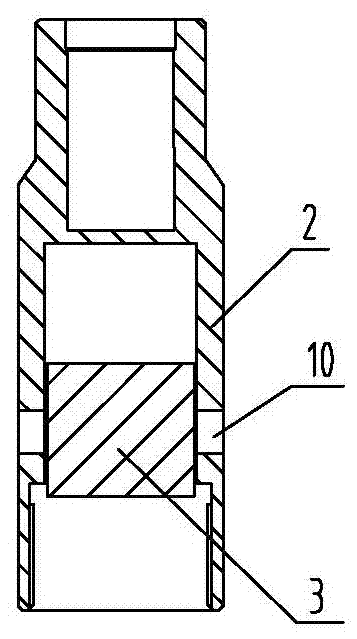
[0009] refer to figure 1 , figure 2 Make the invention. The slide valve plunger oil well pump includes a coupling 1, a double-head threaded joint 4, a plunger 5, a pump cylinder 6 and a plug 8, the upper end of the pump cylinder 6 is fixedly connected to the lower end of the oil pipe 7 through the coupling 1, and the pump cylinder The lower end of 6 is fixedly provided with plug 8, and plunger 5 is arranged in the chamber of pump cylinder 6, and the outer diameter of plunger 5 and the internal diameter of pump cylinder 6 are adapted, and it is characterized in that: the bottom of inner chamber of plunger 5 and The bottom of the inner cavity of the pump cylinder 6 is connected, the upper end of the plunger 5 is fixedly connected with the lower end of the oil outlet cover 2 through the double-ended threaded joint 4, the upper end of the oil outlet cover 2 is fixedly connected with the lower end of the sucker rod 9, and the oil outlet cover 2 The top of the inner chamber is cl...


PUM


Abstract

The invention discloses a sliding valve type plunger oil-well pump which comprises a coupling, a double-head thread connector, a plunger, a pump cylinder and a screwed plug. The upper end of the pump cylinder is fixedly connected with the lower ends of oil pipes through the coupling, and the screwed plug is fixedly arranged at the lower end of the pump cylinder. The sliding valve type plunger oil-well pump is characterized in that the bottom of an inner cavity of the plunger communicates with the bottom of an inner cavity of the pump cylinder; the upper end of the plunger is fixedly connected with the lower end of an oil outlet cover through the double-head thread connector; the upper end of the oil outlet cover is fixedly connected with the lower end of a sucker rod; the top of an inner cavity of the oil outlet cover is closed; a sliding block is arranged in the inner cavity of the oil outlet cover; oil outlet holes are formed in the side walls of the oil outlet cover; an oil inlet hole is formed in the side wall of the lower portion of the pump cylinder; the distance from the oil outlet holes to the top of the inner cavity of the oil outlet cover is larger than or equal to the height of the sliding block; and the position, in the cavity of the pump cylinder, of the plunger is matched with the oil inlet hole in the side wall of the pump cylinder. According to the sliding valve type plunger oil-well pump, the structure is simpler, machining difficulty and machining cost are reduced, multiple problems such as puncture leakage, sand clamping and air lock are effectively solved, and the use period is effectively prolonged.

Description

technical field [0001] The invention relates to an improvement of a plunger oil pump used for well fluid lifting, in particular to a slide valve type plunger oil pump. Background technique [0002] In the oilfield development process, the plunger oil well pump is one of its main lifting equipment. The traditional plunger oil well pumps are equipped with fixed valves and floating valves. These valves are equipped with valve balls and valve seats. The disadvantages are: due to the influence of well conditions and water hammer effect, during the operation of the plunger pump, the valve seat is prone to leaking, the valve ball is not tightly set, etc., resulting in reduced pump efficiency or failure, and prone to occurrence of Air lock and sand stuck phenomenon; in the process of manufacturing, the cost ratio of valve ball and valve seat is relatively high. Contents of the invention [0003] The purpose of the present invention is to provide a slide valve type plunger oil wel...

Claims


Application Information

Patent Timeline
Patent Type & Authority Applications(China)
IPC IPC(8): E21B43/00F04B47/00F04B47/12F04B53/00
CPCE21B43/121F04B47/00F04B47/12F04B53/00
Inventor 马宝忠
Owner SHANDONG WEIMA PUMPS MFG
Why Eureka
Try Eureka