Box beam combined bending moment test mechanism

A technology of box girder and bending moment, applied in the testing of mechanical components, testing of machine/structural components, measuring devices, etc., can solve problems such as single vertical bending moment test

Inactive Publication Date: 2017-07-21
HARBIN ENG UNIV
View PDF5 Cites 9 Cited by
  • Summary
  • Abstract
  • Description
  • Claims
  • Application Information

AI Technical Summary

Problems solved by technology

Although a small number of small-scale model test mechanisms for high-strength steel have been developed, they can only be used fo...

Method used


Image

  • Box beam combined bending moment test mechanism
  • Box beam combined bending moment test mechanism
  • Box beam combined bending moment test mechanism

Examples


Embodiment Construction

[0022] The present invention will be further described in detail below in conjunction with the accompanying drawings and specific embodiments.

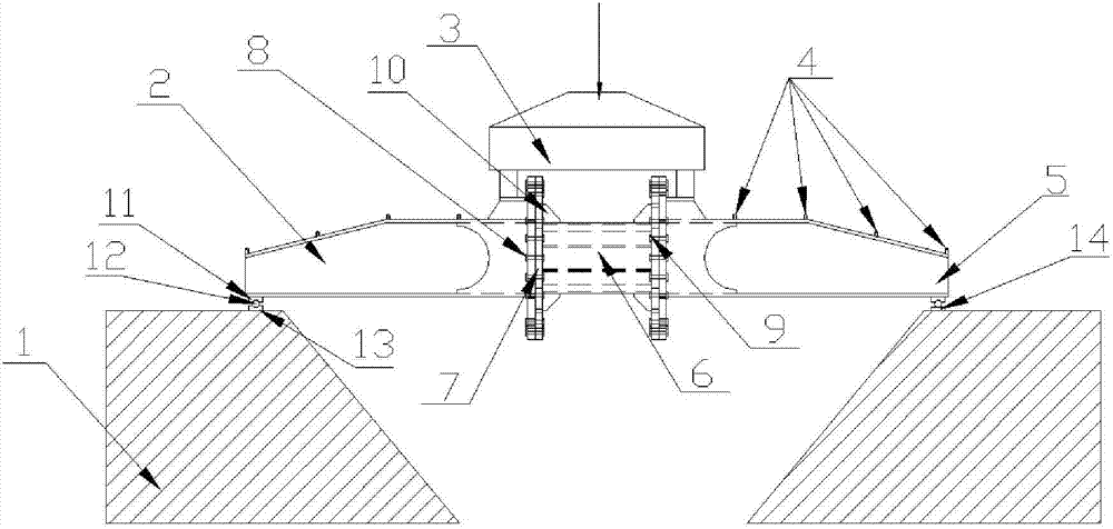
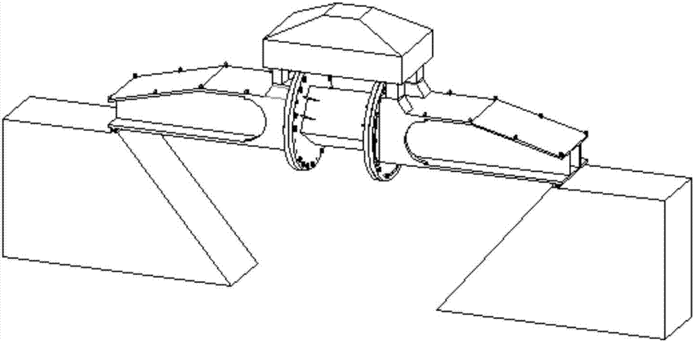
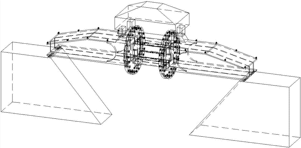
[0023] combine Figure 1 to Figure 11 , the present invention consists of a support base 1, a left connecting bridge 2, a loading structure 3, a lifting lug 4, a right connecting bridge 5, a box beam test piece 6, a disc 7, a bolt 8, a nut 9, and a bracket 10 , upper shaft support 11, roller 12, lower left shaft support 13, lower right shaft support 14 form.

[0024] The support base 1 is placed on the ground, and the left connecting bridge 2 and the right connecting bridge 5 pass through the upper shaft support 11, the roller 12, the lower left shaft support 13 (the lower right shaft support 14) The related mechanisms formed are simply supported on the support base 1 . The left connecting bridge 2 and the right connecting bridge 5 are connected to the disc 7 through the bolt 8 and the nut 9 . The box beam test piece 6 is welded on...


PUM


Abstract

The invention provides a box beam combined bending moment test mechanism. The mechanism comprises a support substrate arranged on the ground, two groups of shaft support seats arranged on left and right ends of the substrate, left and right connection bridges respectively arranged on the two groups of shaft supports, and loading structures arranged on upper ends of the left and right connection bridges. Discs are respectively arranged on the right end of the left connection bridge and the left end of the right connection bridge. A box beam test piece is welded between the discs. The loading structures are arranged on the box beam test piece. According to the invention, combined bending moment test and ultimate strength test under the static strength condition of the box beam can be achieved; and two ends of a model test segment are connected with the connection bridges through the discs and the upper parts are connected with the loading structures, so it is ensured that bending effects are generated under pressure in different angels, demanded experiment data and experiment phenomena are acquired and an experiment objective is achieved.

Description

technical field [0001] The invention relates to a box girder combined bending moment test mechanism, which belongs to the field of box girder bending moment tests. Background technique [0002] A ship is a means of transportation that can sail or berth in waters for transportation or operations. In order to ensure that the designed and built ship can meet the design requirements and sail safely when it encounters or may encounter various external forces, and to make the ship have more economical structural gravity and better constructability, it is usually required that the ship It has a certain strength, so that the ship can not be damaged or deformed within the specified service life. When studying the hull strength, the total longitudinal bending moment and the corresponding total longitudinal bending stress are usually required to calculate the total longitudinal strength of the hull and evaluate the ultimate bending capacity of the hull. Therefore, it is very necessar...

Claims


Application Information

Patent Timeline
IPC IPC(8): G01M13/00
CPCG01M13/00
Inventor 冯国庆常琦任慧龙李陈峰孙树政李辉刘宁许维军周学谦
Owner HARBIN ENG UNIV
Why Eureka
Try Eureka