Safe power supply device

A power supply device and safety technology, applied in the direction of coupling device, two-part connection device, and parts of the connection device, etc., can solve the problems of brewing fire, power failure of electrical equipment, influence of electrical equipment, etc., to prevent accidental power failure , The effect of reducing the risk of fire and ensuring the safety of electricity use

Active Publication Date: 2017-07-21
泰兴市智谷科技孵化器中心
View PDF6 Cites 17 Cited by
  • Summary
  • Abstract
  • Description
  • Claims
  • Application Information

AI Technical Summary

Problems solved by technology

[0002] The power supply head and the power supply seat are used together to supply power to the electrical equipment. The traditional power supply head and the power supply seat use the friction between them to realize the locking of the inserted state, but this locking method is extremely unstable. When working in the power supply state of the electrical equipment, if you accidentally touch the plug, it will be easily disconnected from the socket, resulting in a power outage of the electrical equipment, which will easily affect the electrical equipment, and the traditional power supply head is inserted into the power supply socket. Sparks are often seen at the moment, and this kind of spark is easy to cause a fire when it encounters flammable substances. Therefore, there are great safety hazards in the traditional power supply head and power supply seat. They are all fixed and protrude from the power supply head. Therefore, if they are stepped on when not in use, they are easily bent or even broken, which will affect the use

Method used


Image

  • Safe power supply device
  • Safe power supply device
  • Safe power supply device

Examples


Embodiment Construction

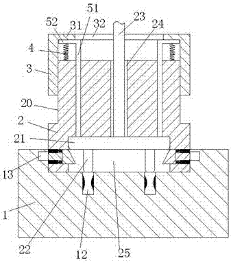
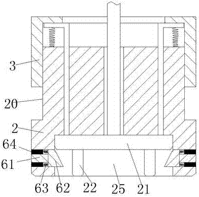
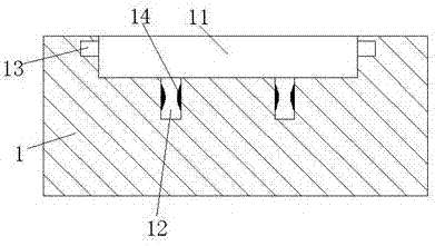
[0018] Combine below Figure 1-5 The present invention will be described in detail.

[0019] refer to Figure 1-5 , a safe power supply device according to an embodiment of the present invention, including a power supply base 1 and a power supply head 2 matched with the power supply base 1, the power supply base 1 is provided with a positioning groove 11 with an upward opening, and the positioning Locking grooves 13 are arranged symmetrically on both side walls of the groove 11, and two symmetrical power supply grooves 12 are arranged at the bottom of the positioning groove 11; A power transmission slider 21 is slidably installed in the sliding groove 25, and two left and right symmetrical power transmission insertion rods 22 are fixedly installed on the lower end of the power transmission slider 21. When the two power transmission insertion rods 22 are inserted into the two power supply slots 12, the Power connection, the upper end wall of the sliding groove 25 is provided ...


PUM


Abstract

The invention provides a safe power supply device which comprises a power supply seat and a power supply head matched with the power supply seat. The power supply seat is internally provided with a positioning groove with an upward opening. Locking grooves are symmetrically arranged in the two side walls of the positioning groove. The bottom of the positioning groove is provided with two power supply grooves in left and right symmetry. The lower end part of the power supply head is provided with a sliding groove with a downward opening. The sliding groove is slidingly equipped with a power transmission sliding block inside. The lower end of the power transmission sliding block is fixedly equipped with two power transmission inserting rods in left and right symmetry. The upper end wall of the sliding groove is provided with two guide grooves in left and right symmetry inside, the two guide grooves communicate with the sliding groove, and each of the guiding grooves is slidingly equipped with a pushing rod inside.

Description

technical field [0001] The invention relates to the field of electric power supply, in particular to a safe power supply device. Background technique [0002] The power supply head and the power supply seat are used together to supply power to the electrical equipment. The traditional power supply head and the power supply seat use the friction between them to realize the locking of the inserted state, but this locking method is extremely unstable. When working in the power supply state of the electrical equipment, if you accidentally touch the plug, it will be easily disconnected from the socket, resulting in a power outage of the electrical equipment, which will easily affect the electrical equipment, and the traditional power supply head is inserted into the power supply socket. Sparks are often seen at the moment, and this kind of spark is easy to cause a fire when it encounters flammable substances. Therefore, there are great safety hazards in the traditional power supp...

Claims


Application Information

Patent Timeline
Patent Type & Authority Applications(China)
IPC IPC(8): H01R13/629H01R13/66H01R13/713H01R24/28H01R24/00
CPCH01R13/62944H01R13/66H01R13/713H01R24/00H01R24/28
Inventor 梁光勇
Owner 泰兴市智谷科技孵化器中心
Why Eureka
Try Eureka