Material conveying manipulator for pharmacy
A technology of manipulator and material pouring, which is applied to manipulators, program-controlled manipulators, manufacturing tools, etc., can solve the problem of labor and other problems, and achieve the effect of convenient installation and disassembly of buckets
- Summary
- Abstract
- Description
- Claims
- Application Information
AI Technical Summary
Problems solved by technology
Method used
Image
Examples
Embodiment 1
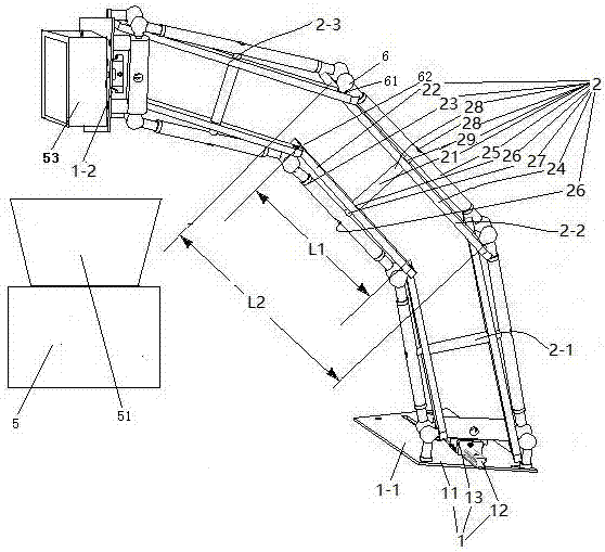
[0028] Embodiment one, see figure 1 , a pharmaceutical dumping manipulator, including a connecting seat assembly 1 and an arm 2.
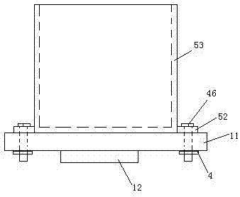
[0029] There are two connecting seat assemblies 1. The two connecting seat assemblies 1 are respectively the first connecting seat assembly 1-1 and the last connecting seat assembly 1-2. Both the first connecting seat assembly 1-1 and the last connecting seat assembly 1-2 include a fixed seat 11, a slide rail 12 arranged on the fixed seat and a movable seat 13 slidably connected to the slide rail. The first connecting seat assembly 1-1 also includes a driving mechanism for driving the movable seat to slide on the slide rail (the driving mechanism is not shown in the figure), and the driving mechanism is an air cylinder. A barrel 53 is fixed on the fixed seat of the last connecting seat assembly 1-2.
[0030] Arm 2 has 3 sections. The three arms 2 are respectively the first arm 2-1, the middle arm 2-2 and the last arm 2-3. The arm 2 includes a fi...
Embodiment 2
[0038] Embodiment two, the difference with embodiment one is:
[0039] see Figure 4 , the driving mechanism 3 provided on the first connecting seat assembly 1 includes a screw rod 32 and a driving motor 33 . One end of the screw rod 32 is threaded on the movable seat 13, and the other end is fixed together with the power output shaft 331 of the driving motor through a connector. A bearing seat 31 supporting the screw rod 32 is also provided on the fixing seat 11 . The connecting seat assembly 1 is also provided with a filler nozzle 9 for filling oil toward the slide bar 12 . During use, the screw mandrel 32 is driven to rotate by the driving motor 33 , and the screw mandrel 32 drives the movable seat 13 to slide on the slide rail 12 .
[0040] see Figure 5 , The filler nozzle 9 includes a filler nozzle body 91 and a filter plate 92 . The fuel nozzle body 91 is a cylindrical structure extending in the vertical direction. A flow channel 911 is provided in the fuel nozzle...
Embodiment 3
[0044] Embodiment three, the difference with embodiment two is:
[0045] see Figure 8 , The driving mechanism is also provided with a control unit 37 and an overload detection switch 38 . The screw rod 32 is provided with a driven helical gear 322 and retaining springs blocking both ends of the driven helical gear 322 to prevent the driven helical gear 322 from moving axially. . A driving helical gear 332 is slidably sleeved on the power output shaft 331 of the driving motor in the axial direction. The driven helical gear 322 meshes with the driving helical gear 332 . A prism section 333 is provided on the power output shaft 331 of the driving motor. The driving helical gear 332 is provided with polygonal holes matching the prism segments. The driving helical gear 332 is axially movably sleeved on the power output shaft 331 of the drive motor and cooperates with the prism section 333 through the polygonal hole to transmit force when sliding and rotating. Both ends of th...
PUM
 Abstract
Description
Claims
Application Information
 - R&D
- Intellectual Property
- Life Sciences
- Materials
- Tech Scout
- Unparalleled Data Quality
- Higher Quality Content
- 60% Fewer Hallucinations
Browse by: Latest US Patents, China's latest patents, Technical Efficacy Thesaurus, Application Domain, Technology Topic, Popular Technical Reports.
© 2025 PatSnap. All rights reserved.Legal|Privacy policy|Modern Slavery Act Transparency Statement|Sitemap|About US| Contact US: help@patsnap.com


