Single-force-source tipper for steel production

A technology for dumping devices and steel, which is applied to furnaces, lighting and heating equipment, furnace components, etc., can solve problems such as labor and labor, and achieve the effect of solving manual feeding

Active Publication Date: 2017-06-13
ZHEJIANG HOUDAR INTELIGENT TECH CO LTD
View PDF4 Cites 2 Cited by
  • Summary
  • Abstract
  • Description
  • Claims
  • Application Information

AI Technical Summary

Problems solved by technology

[0003] The invention provides a single power source dumping device for iron and steel production that only needs one driving structure and can drive each section of the arm to expand and contract, which is used to solve the laborious problem of manually transporting raw materials to the raw material import in the iron and steel production process

Method used


Image

  • Single-force-source tipper for steel production
  • Single-force-source tipper for steel production
  • Single-force-source tipper for steel production

Examples


Embodiment 1

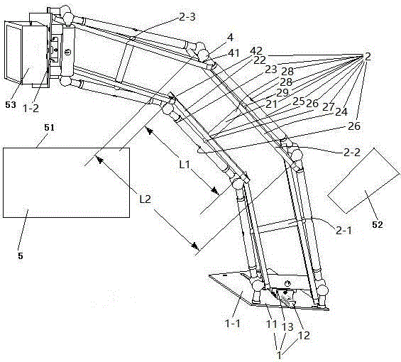
[0024] Embodiment one, see figure 1 , a single power source dumping device for iron and steel production, including a furnace 5 with a raw material inlet at the top, a raw material input pipe 52, a connecting seat assembly 1 and an arm 2.

[0025] The top of the melting furnace 5 is provided with a raw material inlet 51 .

[0026]There are two connecting seat assemblies 1. The two connecting seat assemblies 1 are respectively the first connecting seat assembly 1-1 and the last connecting seat assembly 1-2. Both the first connecting seat assembly 1-1 and the last connecting seat assembly 1-2 include a fixed seat 11, a slide rail 12 arranged on the fixed seat and a movable seat 13 slidably connected to the slide rail. The first connecting seat assembly 1-1 also includes a driving mechanism for driving the movable seat to slide on the slide rail (the driving mechanism is not shown in the figure), and the driving mechanism is an air cylinder. The first connecting seat assembly...

Embodiment 2

[0033] Embodiment two, the difference with embodiment one is:

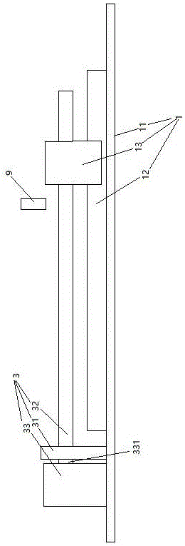
[0034] see figure 2 , the driving mechanism 3 provided on the first connecting seat assembly 1 includes a screw rod 32 and a driving motor 33 . One end of the screw rod 32 is threaded on the movable seat 13, and the other end is fixed together with the power output shaft 331 of the driving motor through a connector. A bearing seat 31 supporting the screw rod 32 is also provided on the fixing base 11 . The connecting seat assembly 1 is also provided with a filler nozzle 9 for filling oil toward the slide bar 12 . During use, the screw mandrel 32 is driven to rotate by the driving motor 33 , and the screw mandrel 32 drives the movable seat 13 to slide on the slide rail 12 .

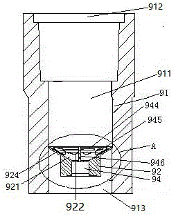
[0035] see image 3 , The filler nozzle 9 includes a filler nozzle body 91 and a filter plate 92 . The fuel nozzle body 91 is a cylindrical structure extending in the vertical direction. A flow channel 911 is provided in the fuel nozzle ...

Embodiment 3

[0039] Embodiment three, the difference with embodiment two is:

[0040] see Image 6 , The driving mechanism is also provided with a control unit 37 and an overload detection switch 38 . The screw rod 32 is provided with a driven helical gear 322 and retaining springs blocking both ends of the driven helical gear 322 to prevent the driven helical gear 322 from moving axially. . A driving helical gear 332 is slidably sleeved on the power output shaft 331 of the driving motor in the axial direction. The driven helical gear 322 meshes with the driving helical gear 332 . A prism section 333 is provided on the power output shaft 331 of the driving motor. The driving helical gear 332 is provided with polygonal holes matching the prism segments. The driving helical gear 332 is axially movably sleeved on the power output shaft 331 of the drive motor and cooperates with the prism section 333 through the polygonal hole to transmit force when sliding and rotating. Both ends of the...


PUM


Abstract

The invention relates to equipment for steel production, and provides a single-force-source tipper for steel production. The single-force-source tipper for steel production comprises two connecting seat assemblies and a plurality of arms, wherein each arm comprises a first external rod, a first internal rod, a second internal rod and a second external rod which are successively arranged in the axial direction of a central shaft; the first internal rod, the second internal rod, the first external rod and the second external rod of one arm are spherically hinged to the first external rod, the second external rod, the first internal rod and the second internal rod of the other arm in a one-to-one correspondence manner; the distance between two hinged points of each first internal rod is smaller than the distance between two hinged points of the corresponding second internal rod; and the first arm is connected with one connecting seat assembly while the last arm is connected with the other connecting seat assembly. The single-force-source tipper for steel production has the advantage that the various arms can be driven to stretch and retract by only one driving structure. The problem that labor is wasted when raw materials are manually conveyed to a raw material inlet in a steel production process is solved.

Description

technical field [0001] The invention relates to equipment for iron and steel production, in particular to a single power source dumping device for iron and steel production. Background technique [0002] In the process of steel production, raw materials need to be input into the furnace for smelting. Existing mechanisms for conveying raw materials such as Figure 7 As shown, it includes a melting furnace 5 with a raw material inlet 51 at the top and a raw material input pipe 52 , and a ramp 54 is provided between the melting furnace 5 and the raw material input pipe 52 . When feeding, the trolley is manually placed under the raw material input pipe, and then the raw material input pipe 52 is opened to load the raw material into the trolley, and then the trolley with the raw material is pushed to the furnace 5 along the ramp by manpower. The top of the material is then poured into the raw material inlet 51. Therefore the existing structure is laborious when feeding. Conte...

Claims


Application Information

Patent Timeline
Patent Type & Authority Applications(China)
IPC IPC(8): F27D3/14
CPCF27D3/14
Inventor 刘小雄邓勇胡普查芮长江侯新宇李昆张钟伟
Owner ZHEJIANG HOUDAR INTELIGENT TECH CO LTD
Why Eureka
Try Eureka