Light source device, illumination device and projector

一种光源装置、照明装置的技术,应用在照明装置、照明装置的冷却/加热装置、放映装置等方向,能够解决寿命缩短、光源部冷却效率不高等问题,达到高效冷却的效果

Inactive Publication Date: 2017-07-25
SEIKO EPSON CORP
View PDF5 Cites 2 Cited by
  • Summary
  • Abstract
  • Description
  • Claims
  • Application Information

AI Technical Summary

Problems solved by technology

[0010] However, solid-state light sources generate heat when they are turned on, and their lifespan is shortened if the high temperature continues, so appropriate cooling is required
[0011] However, in the light source device described in Patent Document 1, for the heat sink disposed on the rear side (the side opposite to the light emitting side) of the light source unit having one or more solid-state light sources, if the heat sink is placed on the rear side of the heat sink, When the cooling gas is sent out from the surface of the light source, only part of the cooling gas will circulate in the light source part, and the other cooling gas will pass through the fins and be discharged without circulating in the light source part.
Therefore, there is a problem that the cooling efficiency of the light source part is not high.

Method used


Image

  • Light source device, illumination device and projector
  • Light source device, illumination device and projector
  • Light source device, illumination device and projector

Examples


no. 1 approach

[0049] Hereinafter, a first embodiment of the present invention will be described with reference to the drawings.

[0050] [Brief composition of the projector]

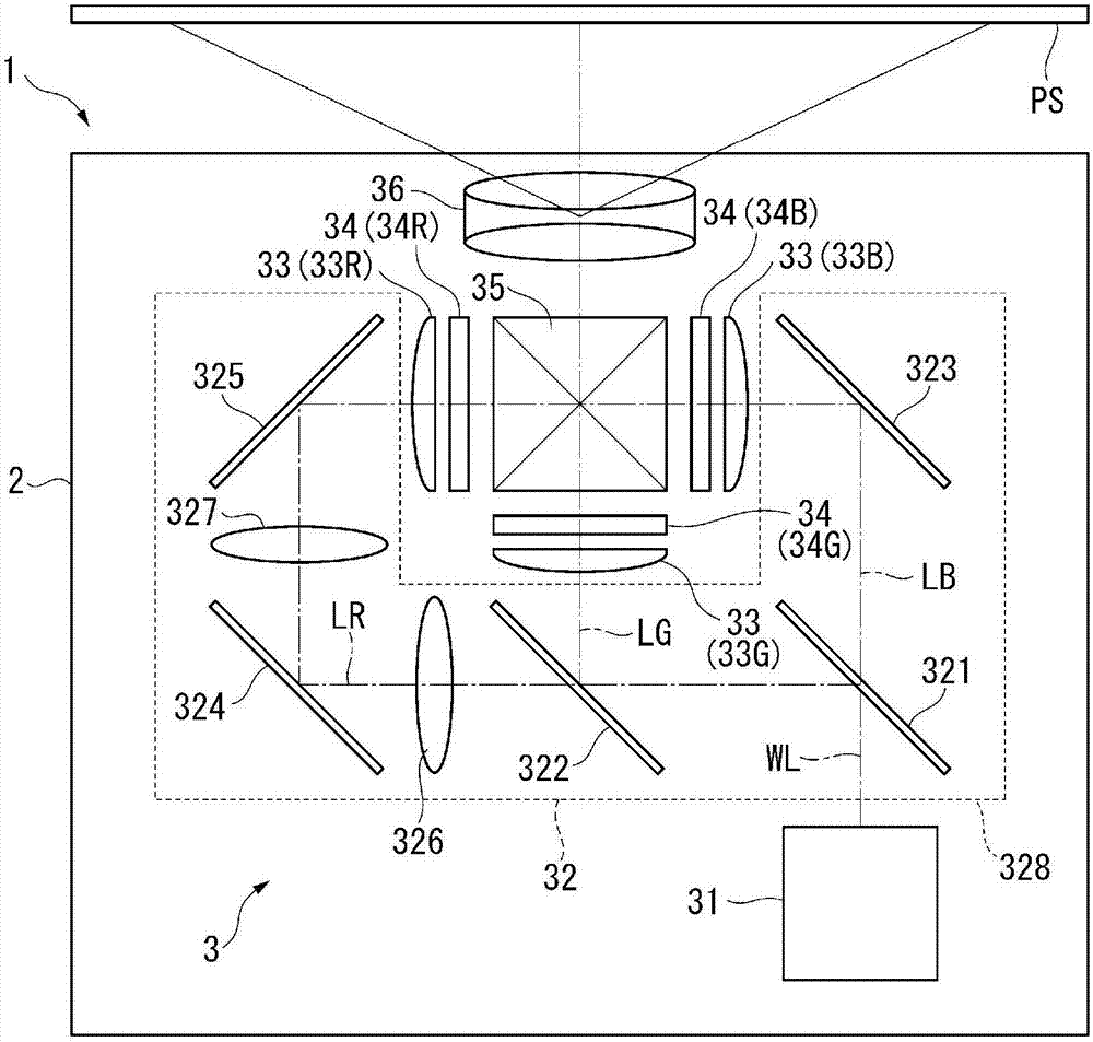
[0051] figure 1 It is a schematic diagram showing the configuration of the projector 1 according to the present embodiment.

[0052] The projector 1 according to the present embodiment is a projection display device that modulates light emitted from a uniform illuminating device 31 described later to form an image corresponding to image information, and enlarges and projects the image onto a screen or the like. On the projection surface PS. like figure 1 As shown, the projector 1 includes an exterior case 2 constituting an exterior package, and an image projection device 3 accommodated in the exterior case 2 . Although not shown in the figure, the projector 1 includes a control device for controlling the projector 1 and a power supply device for supplying electric power to electronic components in addition to a co...


PUM


Abstract

The invention provides a light source device, an illumination device and a projector. The light source device includes a light source portion; a heat receiving portion that receives heat generated in the light source portion; and a heat dissipation portion that dissipates heat conducted from the heat receiving portion, wherein the heat dissipation portion includes a plurality of plate-like bodies that extend out along a plane which is specified by a first direction and a second direction intersecting the first direction, and are disposed facing each other in a third direction intersecting the first direction and the second direction, a connecting portion which is located on the second direction side in the plurality of plate-like bodies, and is connected to the heat receiving portion, an opening which is located on an opposite side to the second direction in the heat dissipation portion, and a position corresponding to the connecting portion, and a shielding portion which is located on an opposite side to the second direction in the heat dissipation portion, and in the periphery of the opening.

Description

[0001] Citations to related applications [0002] The entire contents of Japanese Patent Application No. 2015-257670 filed on December 29, 2015 are hereby incorporated by reference. technical field [0003] The invention relates to a light source device, a lighting device and a projector. Background technique [0004] Currently, there is known a projector comprising: a light source device; a light modulation device for modulating light emitted from the light source device to form an image corresponding to image information; and a projection optical device for enlarging the light on a projected surface such as a screen. Project the resulting image. As a light source device used in such a projector, there is known a light source device that synthesizes laser light in the blue wavelength region and light in the red wavelength region to green wavelength region generated by a fluorescent substance excited by the laser light, thereby White light is emitted (for example, refer to...

Claims


Application Information

Patent Timeline
Patent Type & Authority Applications(China)
IPC IPC(8): G03B21/16G03B21/20
CPCG03B21/16G03B21/20H04N9/3144H04N9/3164G03B21/2013G03B21/2033F21V29/65F21V29/673F21V29/76F21V29/83
Inventor 高城邦彦座光寺诚
Owner SEIKO EPSON CORP
Why Eureka
Try Eureka