
Adjusting mechanism of curved-surface reflection mirror in projector and projector

A curved mirror and adjustment mechanism technology, applied in the field of projectors, can solve problems such as difficult to achieve precise control, cumbersome adjustment steps, and difficult to adjust accurately, so as to achieve better image display effect, realize overall position adjustment, and improve The effect of display quality

Active Publication Date: 2017-07-28
HISENSE
View PDF6 Cites 2 Cited by
  • Summary
  • Abstract
  • Description
  • Claims
  • Application Information

AI Technical Summary

Problems solved by technology

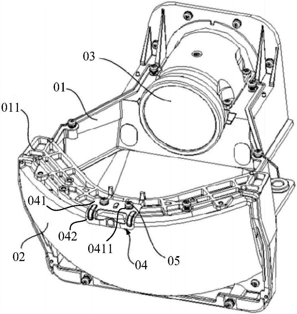
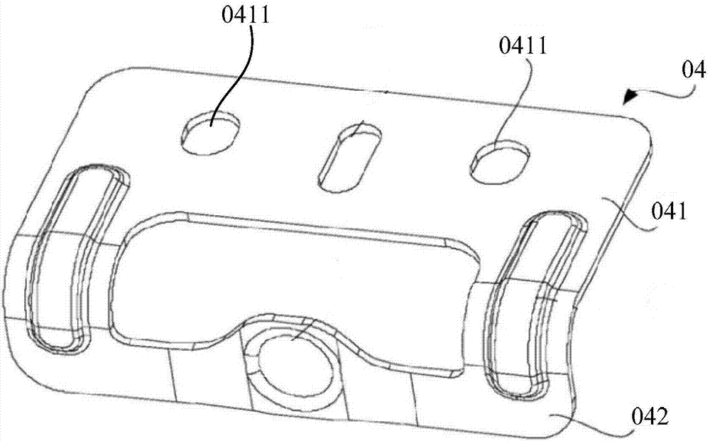
[0005] However, the adjustment mechanism of the curved reflector 02 in the existing projector adjusts the first end of the curved reflector 02 by adjusting the sliding amount of the waist-shaped hole 0411 on the connector 04 relative to the screw 05. To adjust the angle of the curved mirror 02, the angle adjustment of the curved mirror 02 is very small in practice, and it is difficult to precisely control the sliding amount of the waist-shaped hole 0411 of the connector 04 relative to the screw 05, and it is not easy The precise adjustment of the angle of the curved mirror 02 requires repeated adjustments to meet the requirements, which is easy to increase the adjustment time
In addition, before adjusting the first end of the curved mirror 02, it is necessary to loosen the screw 05 so that the waist-shaped hole 0411 on the connecting piece 04 can slide relative to the screw 05. After the adjustment is completed, the screw 05 needs to be tightened so that the connecting piece 04 It is fixed on the arc-shaped support beam 011, which makes the adjustment steps more cumbersome and also increases the adjustment time

Method used


Image

  • Adjusting mechanism of curved-surface reflection mirror in projector and projector
  • Adjusting mechanism of curved-surface reflection mirror in projector and projector
  • Adjusting mechanism of curved-surface reflection mirror in projector and projector

Examples


Embodiment Construction

[0032] The following will clearly and completely describe the technical solutions in the embodiments of the present invention with reference to the accompanying drawings in the embodiments of the present invention. Obviously, the described embodiments are only some, not all, embodiments of the present invention. Based on the embodiments of the present invention, all other embodiments obtained by persons of ordinary skill in the art without making creative efforts belong to the protection scope of the present invention.

[0033] In describing the present invention, it is to be understood that the terms "center", "upper", "lower", "front", "rear", "left", "right", "vertical", "horizontal", The orientations or positional relationships indicated by "top", "bottom", "inner", "outer", etc. are based on the orientations or positional relationships shown in the drawings, and are only for the convenience of describing the present invention and simplifying the description, rather than in...


PUM


Abstract

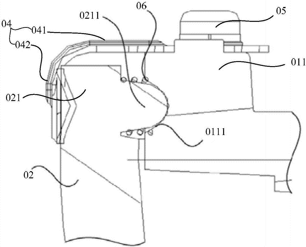
The invention discloses an adjusting mechanism of a curved-surface reflection mirror in a projector and the projector and relates to the technical field of projectors. The objective of the invention is to solve a problem that it is difficult to achieve precise adjustment when the current adjusting mechanism adjusts an upper end of a curved-surface reflection mirror. The adjusting mechanism comprises an installation support and a curved-surface reflection mirror. The upper end of the curved-surface reflection mirror is connected with a first adjusting beam through a fixed beam. The first adjusting beam is fixed on the upper end of the curved-surface reflection mirror. Two first through holes are arranged in the first adjusting beam in the length direction of the first adjusting beam. Two first adjusting screws are threaded in the first through holes respectively, and are in threaded connection with the fixed beam. An elastic piece is arranged between the first adjusting beam and the fixed beam. The contact point of the elastic piece and the first adjusting beam is arranged between the first through holes. The adjusting mechanism can be used for projectors.

Description

technical field [0001] The invention relates to the technical field of projectors, in particular to an adjustment mechanism for a curved reflector in a projector and the projector. Background technique [0002] With the continuous advancement of science and technology, projection display technology has developed rapidly in recent years. Among them, short-focus projection has become the focus of recent research due to the advantages of small projection distance and large projection screen. [0003] At present, one way to realize short-focus projection is reflective short-focus projection, that is, an image is projected on a mirror through a projection lens, and then reflected onto a projection screen by the mirror. Among them, the position of the reflector has become a key factor affecting the projection quality. If the position of the reflector is not installed properly, it will directly affect the projection effect. Therefore, a reflector adjustment mechanism is generally ...

Claims


Application Information

Patent Timeline
IPC IPC(8): G03B21/28
CPCG03B21/28
Inventor 曹秀燕
Owner HISENSE
Learn More