Multi-shaft unmanned aerial vehicle

A drone and airframe technology, applied in the field of drones, can solve problems such as the tilt of the drone fuselage

Active Publication Date: 2017-08-01
SHENYANG WOOZOOM TECH CO LTD
View PDF6 Cites 16 Cited by
  • Summary
  • Abstract
  • Description
  • Claims
  • Application Information

AI Technical Summary

Problems solved by technology

[0003] The purpose of this disclosure is to provide a multi-axis drone to solve the problem of tilting the fuselage of the drone when it moves laterally

Method used


Image

  • Multi-shaft unmanned aerial vehicle
  • Multi-shaft unmanned aerial vehicle
  • Multi-shaft unmanned aerial vehicle

Examples


Embodiment Construction

[0040] The specific embodiments of the present disclosure will be described in detail below with reference to the accompanying drawings. It should be understood that the specific embodiments described herein are only used to illustrate and explain the present disclosure, and are not used to limit the present disclosure.

[0041] In the present disclosure, if no explanation is made to the contrary, the orientation words used such as "up and down" refer to the up and down when the drone is in level flight, and "left and right" refer to the forward direction of the drone. The left and right in flight, "inside and outside" are usually based on the contours of the corresponding parts. In addition, the terms "first", "second" and the like used in the present disclosure are used to distinguish one element from another element, and do not have sequence or importance.

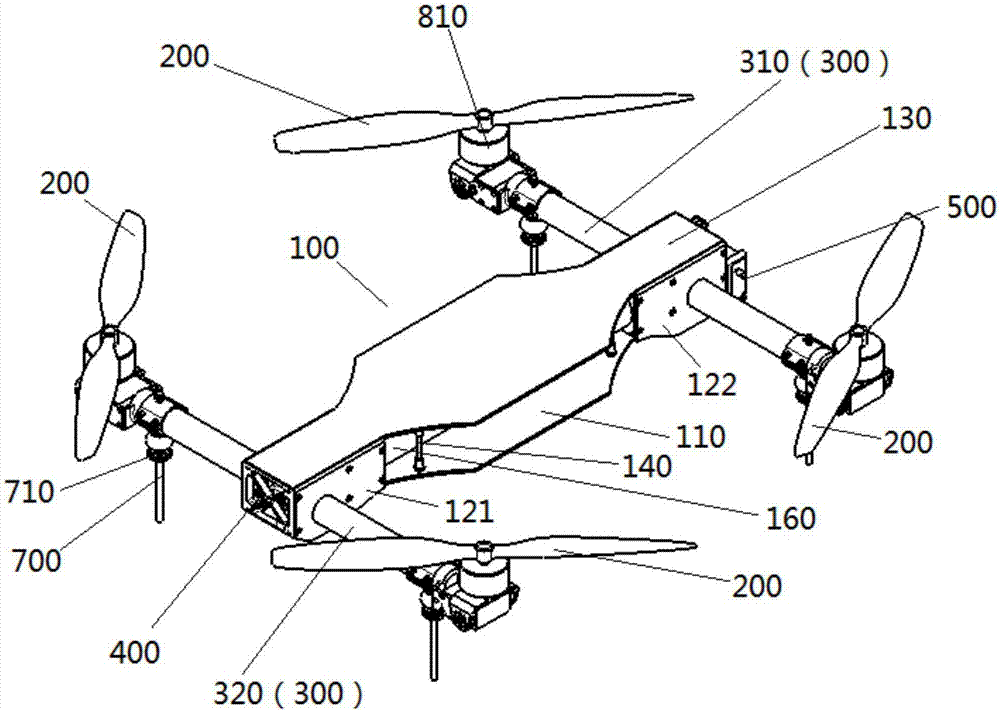
[0042] The multi-axis aircraft provided in the present disclosure refers to an unmanned aerial vehicle with multiple roto...


PUM


Abstract

The invention relates to a multi-shaft unmanned aerial vehicle. The multi-shaft unmanned aerial vehicle comprises a vehicle body (100) and rotor wings (200), wherein support arms (300) are transversally arranged on the vehicle body (100) in a penetrating mode, and the rotor wings (200) are transversally arranged at two ends of each support arm (300). When the unmanned aerial vehicle moves transversally, the tilting rotor wings can provide lifting force to keep the unmanned aerial vehicle at a certain height and also can provide power to drive the unmanned aerial vehicle to move transversally, meanwhile, the vehicle body does not need to incline, and the multi-shaft unmanned aerial vehicle has the advantages of being rapid in response rate and high in flying speed.

Description

Technical field [0001] The present disclosure relates to the technical field of drones, and in particular, to a multi-axis drone. Background technique [0002] Multi-axis UAVs are multi-rotor UAVs, which are mainly different from fixed-wing UAVs. Taking the quadrotor as an example, the working principle of the quadrotor is: the quadrotor changes the rotation speed of the rotor by adjusting the rotation speed of the four driving motors. , To achieve the change of lift, thereby controlling the attitude and position of the aircraft. The existing multi-axis drones have many problems. For example, the overall structure is relatively heavy and the stability is poor; in addition, when the drone changes its attitude and position, the speed of the four brushless motors is adjusted by the flight control system. When the UAV moves in four directions in the horizontal plane, the flight control system must adjust the motor speed to tilt the fuselage to a certain angle before it can move in f...

Claims


Application Information

Patent Timeline
Patent Type & Authority Applications(China)
IPC IPC(8): B64C27/08B64C27/52
CPCB64C27/52B64U10/14B64U20/00B64U30/297B64C27/08B64C39/024B64U10/13B64U30/20B64U50/19B64U2101/30
Inventor 张震梅森杜春水
Owner SHENYANG WOOZOOM TECH CO LTD
Why Eureka
Try Eureka