Endoscope

A technology for endoscopes and components, applied in the field of endoscopes, can solve problems such as difficult configuration

Active Publication Date: 2017-08-01
OLYMPUS CORP
View PDF10 Cites 6 Cited by
  • Summary
  • Abstract
  • Description
  • Claims
  • Application Information

AI Technical Summary

Problems solved by technology

[0005] However, when the wire connection mechanism provided in the drum portion shown in Japanese Patent Application Laid-Open No. 2005-218569 is installed in the operating part of an endoscope shown in Japanese Patent Laid-Open No. 2007-190047 or in Japanese Patent

Method used


Image

  • Endoscope
  • Endoscope
  • Endoscope

Examples


Embodiment Construction

[0027] Hereinafter, embodiments of the present invention will be described with reference to the drawings.

[0028] In addition, in each of the drawings used in the following description, the scale may be different for each component so that each component has a size that can be recognized on the drawing. That is, the present invention is not limited to the number of constituent elements, the shape of the constituent elements, the size ratio of the constituent elements, and the relative positional relationship of the constituent elements described in these drawings.

[0029] refer to Figures 1 to 4C The first embodiment will be described.

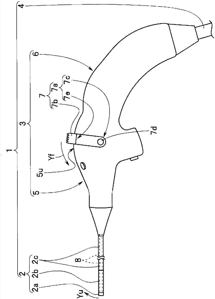
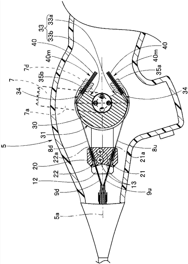
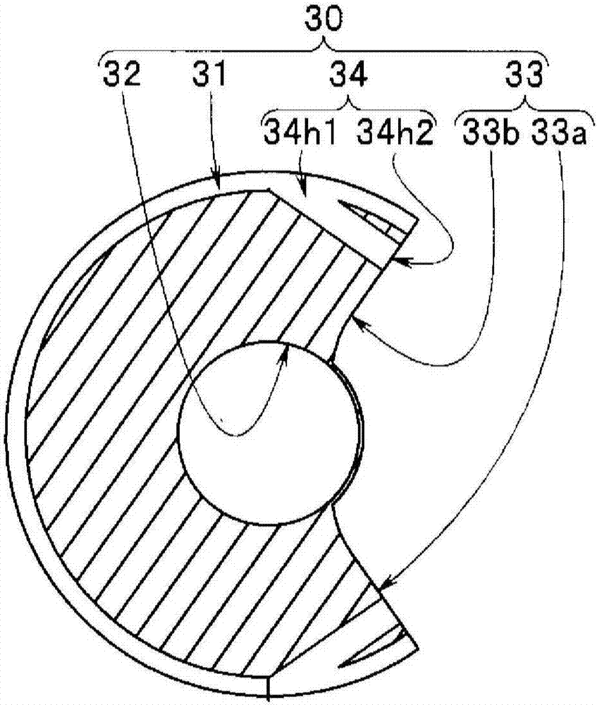
[0030] Such as figure 1 As shown, the endoscope 1 is mainly provided with an insertion unit 2 , a grip operation unit 3 , and a universal cord 4 . The grip operation part 3 is configured by fixing the operation part 5 and the extension part 6 integrally.

[0031] The insertion part 2 is inserted into a nasal cavity, for example. The i...


PUM


Abstract

An endoscope comprises: an insertion section provided with a bendable section on the distal end side thereof, the bendable section being bendable at least in the vertical direction; an operating section to which the proximal end of the insertion section is connected; a pull-wire having a first end and a second end, the first end being connected to the insertion section and being pulled to bend the bendable section; a fixation member affixed to the second end of the pull-wire; a holding member for holding the affixation member; and a pulley provided within the operating section so that the pulley can pivot and having an arrangement section in which the holding member is arranged.

Description

technical field [0001] The present invention relates to an endoscope having a bending lever for pulling / loosening a bending wire on an operating portion. Background technique [0002] Endoscopes capable of observation and the like by inserting an elongated insertion portion into a subject are widely used. Some endoscopes include a type in which a bending portion is provided on the distal end side of an insertion portion. The bending part is generally configured to perform a bending operation by pulling or loosening the bending wire by turning a bending lever provided on the operating part, for example, as a bending operation device. [0003] For example, the endoscope device disclosed in Japanese Patent Application Laid-Open No. 2005-218569 shows a bending wire configured by connecting a pulling wire on one side to a pulling wire on the other side by a wire connecting mechanism. The wire connection mechanism is composed of an external threaded joint fixedly provided with t...

Claims


Application Information

Patent Timeline
IPC IPC(8): A61B1/00G02B23/24
CPCA61B1/0011A61B1/0052A61B1/0057A61B1/233G02B23/24
Inventor 比地原邦彦
Owner OLYMPUS CORP
Why Eureka
Try Eureka