Flange Alignment Tool and Operation Method

An operation method and flange technology, applied in the field of flange alignment tools, can solve the problems of fragile components, sealing rings and gaskets, difficult insertion of bolts, and difficult alignment work, and achieve flexible adjustment and accurate alignment. Effect

Active Publication Date: 2018-09-18
HEBEI IRON AND STEEL
View PDF5 Cites 0 Cited by
  • Summary
  • Abstract
  • Description
  • Claims
  • Application Information

AI Technical Summary

Problems solved by technology

Due to the heavy weight of components and pipes, it is very difficult to adjust the position during the process of precise alignment, which will easily lead to flange misalignment and difficult installation
In addition, after the equipment has been in operation for a long time, the pipeline may be bent and deformed due to stress and heat. When the installation is resumed after disassembly and maintenance, the misalignment of the flanges will be more obvious. It often happens that the flanges cannot be aligned accurately, the bolts are difficult to insert, and the bolts are tightened. Gaskets are easily damaged when bolts are fastened
[0003] At present, for small-diameter pipes, flange alignment is generally done manually with traditional crowbars, which is time-consuming and labor-intensive, and is easy to damage components, sealing rings and gaskets, resulting in leakage
When aligning large pipelines, engineering machinery such as cranes, jacks, and gantry frames are generally used to assist in the alignment. However, this method is often limited by the site, and the alignment work is even more difficult when the installation space for large pipelines is small.

Method used


Image

  • Flange Alignment Tool and Operation Method
  • Flange Alignment Tool and Operation Method
  • Flange Alignment Tool and Operation Method

Examples


Embodiment 1

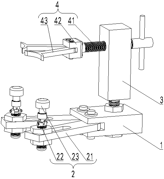
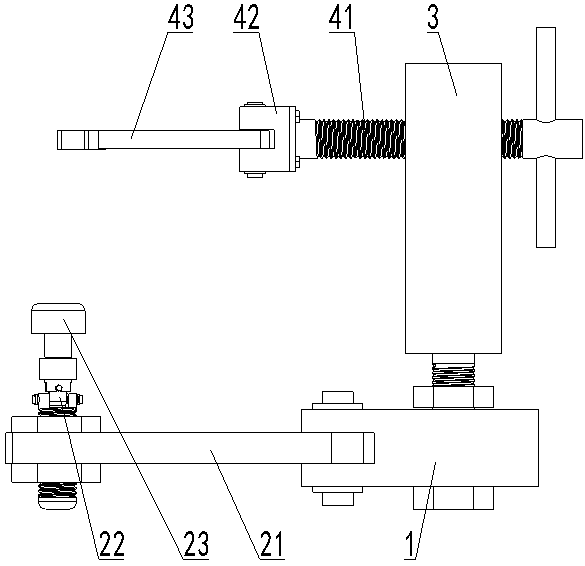
[0076] A flange alignment tool includes a base 1 , a positioning mechanism 2 , a connecting rod 3 and an alignment mechanism 4 . One end of the positioning mechanism 2 is connected to the base 1 , and the other end is suitable for connecting to the bolt hole of the first flange 5 . The connecting rod 3 is vertically connected to the base 1 , and the connecting rod 3 can be adjusted up and down relative to the base 1 . One end of the alignment mechanism 4 is disposed on the connecting rod 3 , and the other end can abut against the second flange 6 . The alignment mechanism 4 can be adjusted in an axial direction perpendicular to the second flange 6 relative to the connecting rod 3 . The alignment mechanism 4 is arranged parallel to the positioning mechanism 2 .

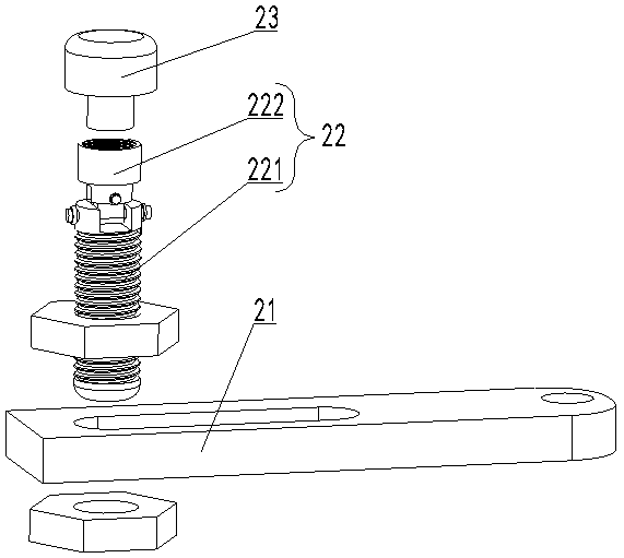
[0077] The positioning mechanism 2 includes a pull rod 21 , a connecting mechanism 22 and a column hook 23 . One end of the pull rod 21 is connected to the base 1, and the other end is provided with a sliding groove....

Embodiment 2

[0085] A flange alignment tool includes a base 1 , a positioning mechanism 2 , a connecting rod 3 and an alignment mechanism 4 . One end of the positioning mechanism 2 is connected to the base 1 , and the other end is suitable for connecting to the bolt hole of the first flange 5 . The connecting rod 3 is vertically connected to the base 1 , and the connecting rod 3 can be adjusted up and down relative to the base 1 . One end of the alignment mechanism 4 is disposed on the connecting rod 3 , and the other end can abut against the second flange 6 . The alignment mechanism 4 can be adjusted in an axial direction perpendicular to the second flange 6 relative to the connecting rod 3 . The alignment mechanism 4 is arranged parallel to the positioning mechanism 2 .

[0086] The positioning mechanism 2 includes a pull rod 21 , a connecting mechanism 22 and a column hook 23 . One end of the pull rod 21 is connected to the base 1, and the other end is provided with a sliding groove....

Embodiment 3

[0091] A flange alignment tool includes a base 1 , a positioning mechanism 2 , a connecting rod 3 and an alignment mechanism 4 . One end of the positioning mechanism 2 is connected to the base 1 , and the other end is suitable for connecting to the bolt hole of the first flange 5 . The connecting rod 3 is vertically connected to the base 1 , and the connecting rod 3 can be adjusted up and down relative to the base 1 . One end of the alignment mechanism 4 is disposed on the connecting rod 3 , and the other end can abut against the second flange 6 . The alignment mechanism 4 can be adjusted in an axial direction perpendicular to the second flange 6 relative to the connecting rod 3 . The alignment mechanism 4 is arranged parallel to the positioning mechanism 2 .

[0092] The connecting rod 3 is located on one side of the base 1, the base 1 is provided with a first threaded through hole, and the end of the connecting rod 3 close to the base 1 is provided with a threaded through ...


PUM


Abstract

The invention belongs to the technical field of auxiliary mounting, and particularly relates to a flange alignment tool and an operation method. The flange alignment tool comprises a base, positioning mechanisms, a connecting rod and an alignment mechanism, wherein one end of each positioning mechanism is connected with the base, and the other end of the corresponding positioning mechanism is suitable for being connected with a bolt hole of a first flange; the connecting rod is vertically connected with the base, and can be longitudinally adjusted relative to the base; one end of the alignment mechanism is arranged on the connecting rod, and the other end of the alignment mechanism can be abutted against a second flange; the alignment mechanism can be adjusted along the axial direction perpendicular to the second flange, relative to the connecting rod; and the alignment mechanism and the positioning mechanisms are in parallel arrangement. Through the adoption of the flange alignment tool, flanges can be rapidly aligned. The flange alignment tool has the advantages of being flexible in adjustment, and small in space of occupation.

Description

technical field [0001] The invention belongs to the technical field of auxiliary installation, in particular to a flange alignment tool and an operation method. Background technique [0002] Flange connection is a commonly used connection method between components and pipes. During installation, after the flanges are roughly aligned, precise alignment is required to install the connecting bolts for fastening. Due to the heavy weight of components and pipes, it is very difficult to adjust the position during the process of precise alignment, which will easily lead to flange misalignment and difficult installation. In addition, after the equipment has been in operation for a long time, the pipeline may be bent and deformed due to stress and heat. When the installation is resumed after disassembly and maintenance, the misalignment of the flanges will be more obvious. It often happens that the flanges cannot be aligned accurately, the bolts are difficult to insert, and the bolts...

Claims


Application Information

Patent Timeline
Patent Type & Authority Patents(China)
IPC IPC(8): B25B11/02
CPCB25B11/02
Inventor 周晓龙吴戈赵海平李伟志商仕金
Owner HEBEI IRON AND STEEL
Why Eureka
Try Eureka