
Variable vehicle wheel applied to center position of robot and center position adjusting method

A center position, robot technology, applied in the field of robotics, can solve the problems that cannot be fully promoted, cannot improve the robot's walking adaptability, poor absorption capacity, etc., and achieve the effect of improving the walking adaptability

Active Publication Date: 2017-08-04
NANJING UNIV OF POSTS & TELECOMM
View PDF5 Cites 5 Cited by
  • Summary
  • Abstract
  • Description
  • Claims
  • Application Information

AI Technical Summary

Problems solved by technology

[0002] With the advancement of science and technology, the robot walking mechanism has begun to be applied, but the existing robot walking mechanism has poor adaptability to the road surface due to the limitation of the structure. Restricted, cannot be fully promoted
With the deepening of robot research, the wheels of robots are currently supported by elastic suspensions. However, the rough road surface of this kind of wheels has poor absorption capacity, which still cannot improve the walking adaptability of robots in complex environments.

Method used


Image

  • Variable vehicle wheel applied to center position of robot and center position adjusting method
  • Variable vehicle wheel applied to center position of robot and center position adjusting method
  • Variable vehicle wheel applied to center position of robot and center position adjusting method

Examples


Embodiment approach 1

[0057] Embodiment 1: each linear expansion device is preferably a servo electric cylinder.

Embodiment approach 2

[0058] Embodiment 2: each linear expansion device is preferably a cylinder.

Embodiment approach 3

[0059] Embodiment 3: each linear expansion device is preferably an elastic damping element.

[0060] As an alternative, the several linear expansion devices in the centering mechanism can also be a combination of servo electric cylinders and air cylinders.

[0061] Such as Figure 6 As shown, the working principle is: by controlling the length expansion and contraction of each linear expansion device, the adjustment of the center position is realized, and the center distance is ex, ey, so that the center position can be dynamically controlled.

[0062] A method for adjusting the center position of a wheel with a variable center position. The center position of the wheel is adjusted according to the road environment conditions on which the robot is driving. The specific adjustment method is as follows.

[0063] 1) if Figure 7 As shown, when the robot is driving on a level ground, by controlling the length expansion and contraction of each linear expansion device, the line conn...


PUM


Abstract

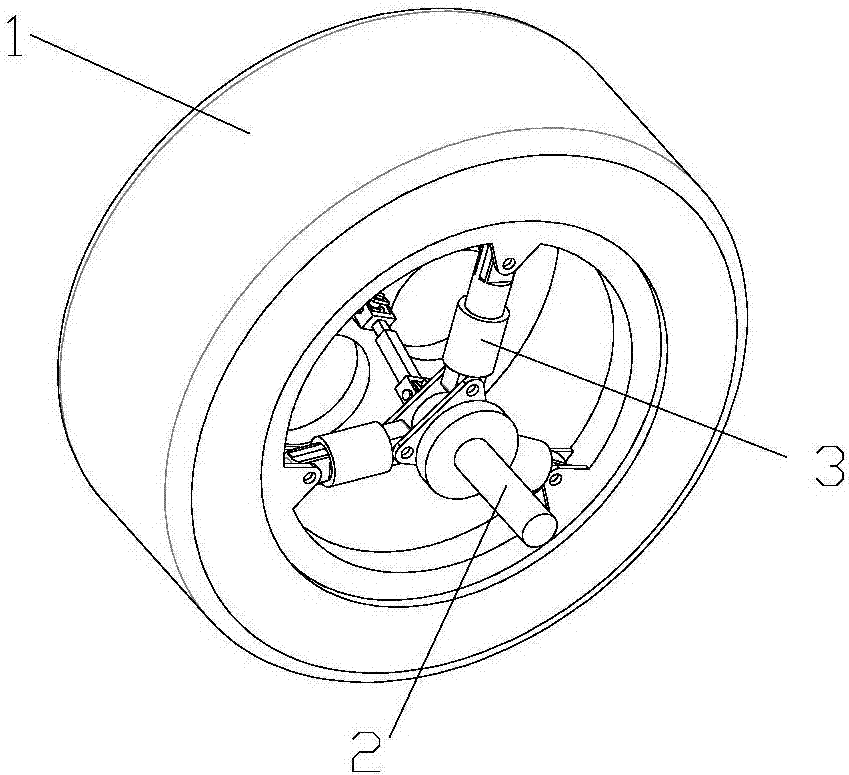
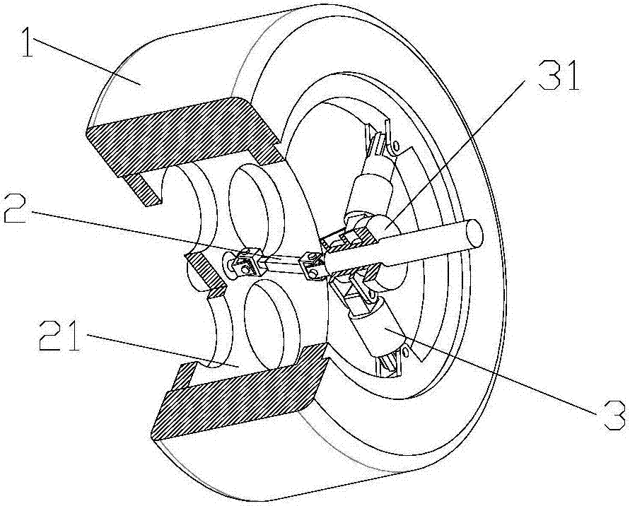
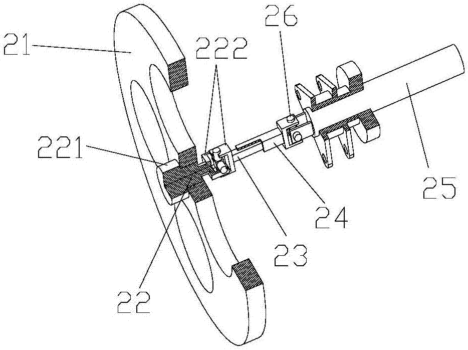
A variable vehicle wheel applied to the center position of a robot and a center position adjusting method comprise an outer wheel ring, a universal transmission mechanism and a self-aligning mechanism. The universal transmission mechanism comprises a connecting disc, a connecting shaft, a transmission rod and a driving shaft; the connecting disc is coaxially fixed to the periphery of the connecting shaft in a sleeved mode and is fixedly connected with the outer wheel ring; the length of the transmission rod is telescopic, one end of the transmission rod is movably connected with the connecting shaft, and the other end is movably connected with the transmission shaft; the aligning mechanism comprises an inner wheel ring and a plurality of linear telescopic devices; the inner wheel ring is coaxially fixed to the transmission shaft in a sleeved mode and can be fixedly connected with a rack; the inner wheel ring serves as the center for multiple linear telescopic devices, and the linear telescopic devices are distributed between the outer wheel ring and the inner wheel ring in a radiating shape; and one end of each linear telescopic device is hinged to the outer wheel ring, and the other end of each linear telescopic device is hinged to the inner wheel ring. The variable vehicle wheel applied to the center position of the robot and the center position adjusting method can realize dynamic control of the center position of the driving shaft in a wheel, and can greatly improve the walking adaptability in a complex environment of the robot.

Description

technical field [0001] The invention relates to the technical field of robots, in particular to a wheel with a variable center position applied to a robot and a method for adjusting the center position. Background technique [0002] With the advancement of science and technology, the robot walking mechanism has begun to be applied, but the existing robot walking mechanism has poor adaptability to the road surface due to the limitation of the structure. Limited, cannot be fully promoted. With the deepening of robot research, the wheels of robots are currently supported by elastic suspensions. However, such wheels have poor absorption capacity for rough roads, which still cannot improve the walking adaptability of robots in complex environments. Contents of the invention [0003] The technical problem to be solved by the present invention is to provide a wheel with a variable center position applied to a robot for the above-mentioned deficiencies in the prior art. The wheel...

Claims


Application Information

Patent Timeline
IPC IPC(8): B60B19/00B62D57/02
Inventor 徐丰羽蒋国平
Owner NANJING UNIV OF POSTS & TELECOMM
Learn More