An overheat protection device

An overheating protection and overheating technology, applied in the direction of heating/cooling contact switch, etc., can solve the problems of loose battery electrode connection, thermal runaway of power battery, and ineffective thermal control sheet, etc., to achieve reasonable layout and increase contact area , low cost effect

Active Publication Date: 2019-12-06
李天羿
View PDF5 Cites 0 Cited by
  • Summary
  • Abstract
  • Description
  • Claims
  • Application Information

AI Technical Summary

Problems solved by technology

Specific cases of power battery fires include thermal runaway of the power battery caused by overcharging of the battery, electrolyte leakage, causing a short circuit, and resulting in a fire; there is a case where the electrode connection of the battery cell is loose, and then the thermal control plate does not work, causing the battery to heat up, resulting in a fire.

Method used


Image

  • An overheat protection device
  • An overheat protection device
  • An overheat protection device

Examples


Embodiment 1

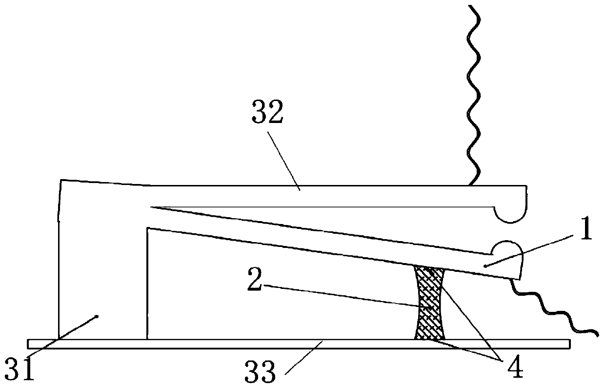
[0044] An overheating protection device, including a plastic element 2 and an elastic auxiliary assembly, the elastic auxiliary assembly includes a support and a spring 1 connected to the support at one end, and the plastic element 2 is connected between the support and the spring 1 so that the spring 1 is in energy storage state, and when overheated, it will be pulled and broken, so that the spring 1 releases energy. Both the spring 1 and the support are equipped with electrodes 5 for connecting with the alarm. The two electrodes 5 are in contact when the spring 1 releases energy, and the alarm is turned on. .

[0045] The material of the plastic element 2 can be selected from plastic materials with different melting temperatures according to the temperature requirements of its applied working conditions, such as polycaprolactone, polyvinyl chloride, polyethylene, polypropylene, nylon or polyoxymethylene, etc., and can also be blended, Filling, crosslinking, reinforcement, co...

Embodiment 2

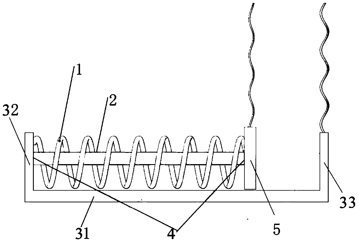
[0055] An overheating protection device, including a plastic element 2 and an elastic auxiliary assembly, the elastic auxiliary assembly includes a support and a spring 1 connected to the support at one end, and the plastic element 2 is connected between the support and the spring 1 so that the spring 1 is in energy storage state, and when overheated, it will be pulled and broken, so that the spring 1 releases energy. Both the spring 1 and the support are equipped with electrodes 5 for connecting with the alarm. The two electrodes 5 are in contact when the spring 1 releases energy, and the alarm is turned on. .

[0056] The support in this embodiment includes a support body in the shape of a "匚", the support body is composed of a connecting plate 31 and a first wing plate 32 and a second wing plate 33 arranged at both ends of the connecting plate 31, the spring 1 And the plastic element 2 is arranged in the semi-enclosed space surrounded by the support. Wherein, the spring 1 ...

Embodiment 3

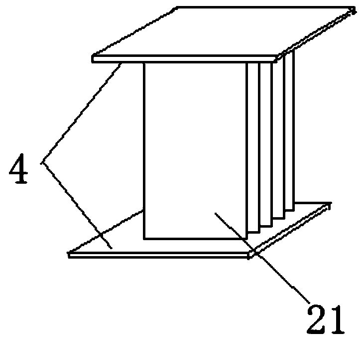
[0065] This embodiment is basically the same as Embodiment 2, except that the plastic element 2 in this embodiment is in the shape of a multi-layer film, including a plurality of parallel plastic films 21, and there is a gap between two adjacent plastic films 21. Such as image 3 shown.


PUM


Abstract

The invention relates to an overheating protective device comprising a plastic element (2) and an elastic auxiliary component which further comprises a support and a spring (1), of which one end is connected to the support. The plastic element (2) is connected between the support and the spring (1) so that the spring (1) is in an energy storage state and is subjected to a tensile fracture at the time of overheating to release the energy of the spring (1). The spring (1) and the support are both provided with electrodes (5) for connection with an alarm, and the two electrodes (5) are in contact when the energy is released from the spring (1) so as to turn on the alarm. Compared with overheating protective devices in the prior art, the overheating protective device of the invention is low in cost, extensive in applicability, simple in structure, reasonable in layout, small in occupation space, high in normal temperature reliability and alarm reliability, fast in response speed and low in wrong touch rate.

Description

technical field [0001] The invention relates to an overheat protection device, in particular to an auxiliary overheat protection device for new energy vehicles. Background technique [0002] If the temperature is out of control, it will cause serious consequences such as fire and explosion. Overheating protection means that when the temperature exceeds a certain threshold, the corresponding protection function will be activated. At present, overheating protection generally uses heat-sensitive electronic components or bimetallic strips to form an overheating protection circuit to realize the function of overheating protection. It has the advantages of intelligence and reusability, and is the current mainstream technology. However, there are reliability problems in electronic components and bimetallic strips, and once they fail, serious consequences will result. [0003] New energy vehicles refer to vehicles that use unconventional vehicle fuels as the power source and adopt ...

Claims


Application Information

Patent Timeline
Patent Type & Authority Patents(China)
IPC IPC(8): H01H37/76
CPCH01H37/76
Inventor 李天羿
Owner 李天羿
Why Eureka
Try Eureka