
Key bit groove milling device

A milling device, the technology of the key head, applied in the direction of milling machine equipment, milling machine equipment details, metal processing equipment, etc.

Active Publication Date: 2017-08-11
江门市凯骏机电有限公司
View PDF5 Cites 0 Cited by
  • Summary
  • Abstract
  • Description
  • Claims
  • Application Information

AI Technical Summary

Problems solved by technology

[0003] In order to solve the above problems, the object of the present invention is to provide a key head groove milling device. When the key heads are batch milled, the key heads can be stably placed in the feed rack, and the problem of key head falling will not occur. And the push plate can be firmly fixed on the cylinder shell on the cylinder support arm in the milling cylinder, and there will be no problem that the push plate is gradually detached from the pneumatic component and the position will be shifted, so it will not affect the key head milling device. work effectively

Method used


Image

  • Key bit groove milling device
  • Key bit groove milling device
  • Key bit groove milling device

Examples


Embodiment Construction

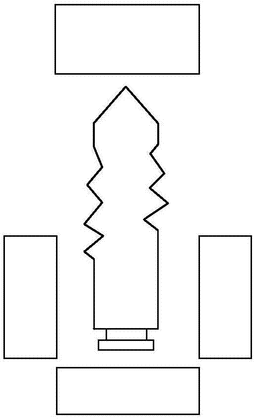
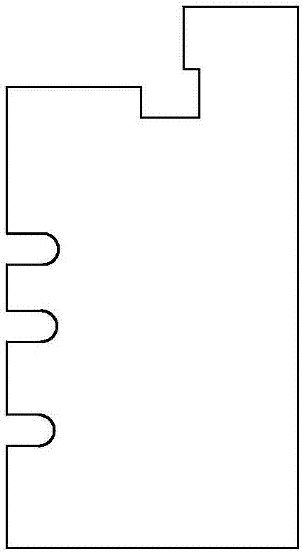
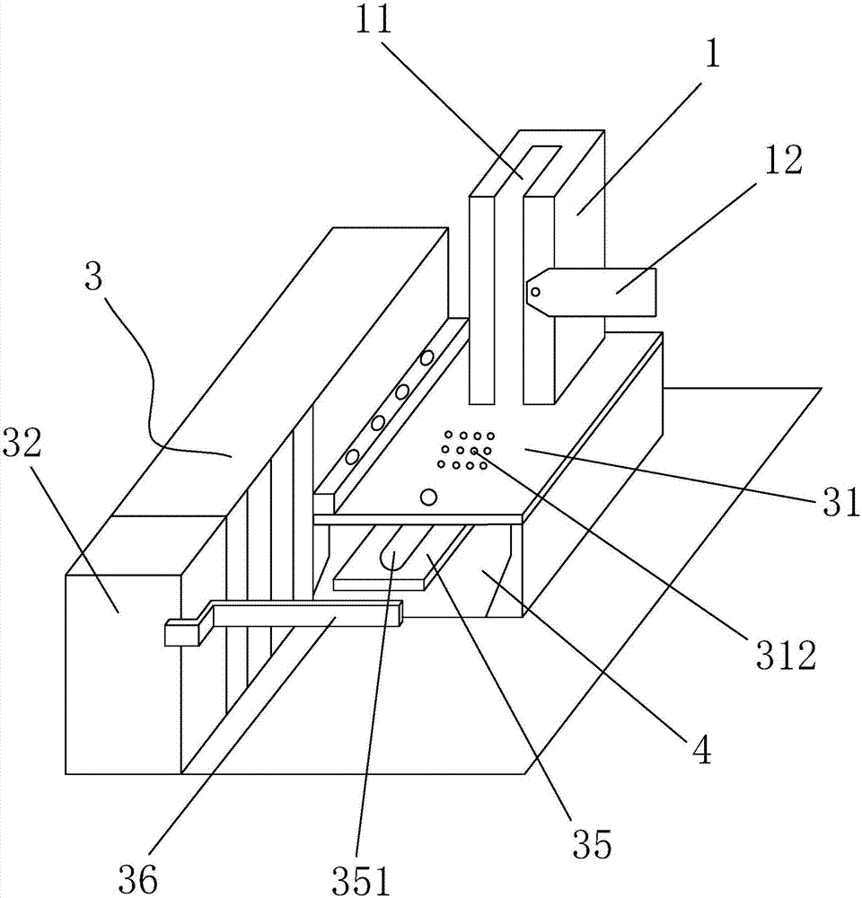
[0017] refer to Figure 3-Figure 5 , a kind of key bit milling device of the present invention, comprises the feeding frame 1 that is used for placing key bit in batches that is integrally formed, the milling cutter 2 that is used for carrying out milling processing to key bit, is used for pushing key bit to milling machine. Knife 2 carries out the pushing device 3 of slot milling processing and is used for the discharge outlet 4 that the key head that completes slot milling process is discharged, is provided with the feed slot 11 that shape matches with the key head in the feed frame 1, feed slot 11. An opening is provided at the end of the key head. The pushing device 3 includes a push plate 31 for transporting the key head and a milling cylinder 32 for driving the push plate 31 to move back and forth. On the cylinder support arm of the milling cylinder 32 A cylinder casing is provided, and the push plate 31 is provided with a circular through hole 311. The push plate 31 is ...


PUM


Abstract

The invention discloses a key bit groove milling device. The key bit groove milling device comprises a feeding rack, a milling cutter, a pushing device and a discharging outlet. A feeding groove is formed in the feeding rack, and an opening is formed in the feeding groove and located at the tail position of a key bit. The pushing device comprises a pushing plate and a groove milling cylinder. A cylinder shell is arranged above a cylinder support arm of the groove milling cylinder. The pushing plate is provided with round through holes, is further fixed above the cylinder shell by means of locking of bolts and the round through holes and can move front and back along with the cylinder support arm. When being subjected to batch groove milling, the key bit can be stably located inside the feeding rack, and the disengaging problem of the key bit can be avoided; and moreover, the pushing plate can be firmly fixed above the cylinder shell on the cylinder support arm located in the groove milling cylinder, the problem that the pushing plate is gradually disengaged from a pneumatic assembly to cause location deviation cannot happen, and thus effective work of the key bit groove milling device cannot be influenced.

Description

technical field [0001] The invention relates to the field of key processing equipment, in particular to a key head groove milling device. Background technique [0002] A key with a key shell is generally composed of a key head and a key shell. To make such a key, it is first necessary to mill the teeth and slots of the key head, and finally assemble the key head into the key shell. When milling the key head, in the existing key head milling machine, the feed frame used to prevent the key head is generally composed of a front bar, a rear bar, a left bar and a right bar. Wherein the back bar, the left bar and the right bar are close together and are used to limit the position of the key head, and there is a gap between the front bar and the left bar and the right bar for putting the key head into it. However, when the milling machine mills the key head, it will be accompanied by vibration, and as the milling progresses, the key head is very easy to fall from the gap, which wi...

Claims


Application Information

Patent Timeline
Patent Type & Authority Applications(China)
IPC IPC(8): B23C3/35
CPCB23C3/35
Inventor 李润旋
Owner 江门市凯骏机电有限公司
Learn More