
an injection mold

A technology of injection molds and inserts, applied in the direction of coating, etc., can solve the problems of reducing product quality, unable to work, affecting production and processing work, etc., to achieve the effect of improving injection molding ability and ensuring quality

Active Publication Date: 2019-04-05
ZHEJIANG BUSINESS TECH INST
View PDF4 Cites 1 Cited by
  • Summary
  • Abstract
  • Description
  • Claims
  • Application Information

AI Technical Summary

Problems solved by technology

If the installation and fixing mechanism is not stable and reliable enough, the insert will be out of the original position when the film is laminated, which will cause the mold to be damaged
Moreover, it will also cause the ABS plastic melt to follow the axial runner to other positions of the mold, making the work impossible, and the operator must write down the mold to clean it up.
This not only affects the production and processing work, but also seriously reduces the quality of the product

Method used


Image

  • an injection mold
  • an injection mold
  • an injection mold

Examples


Embodiment Construction

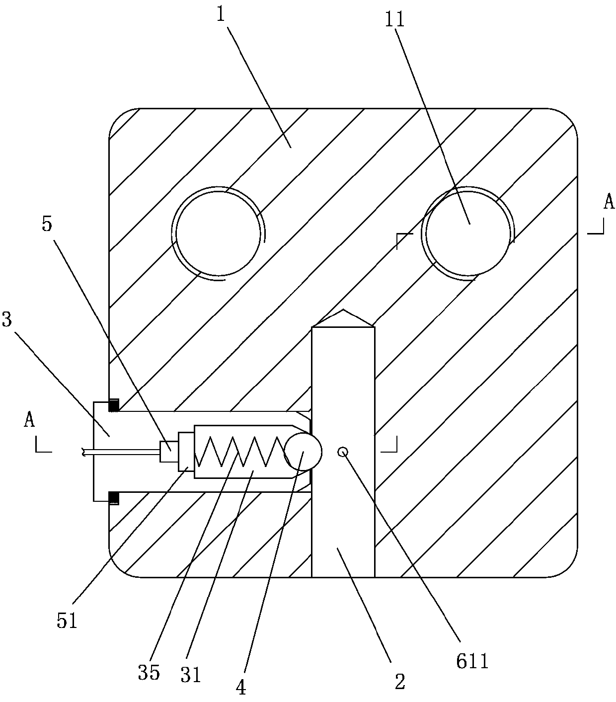
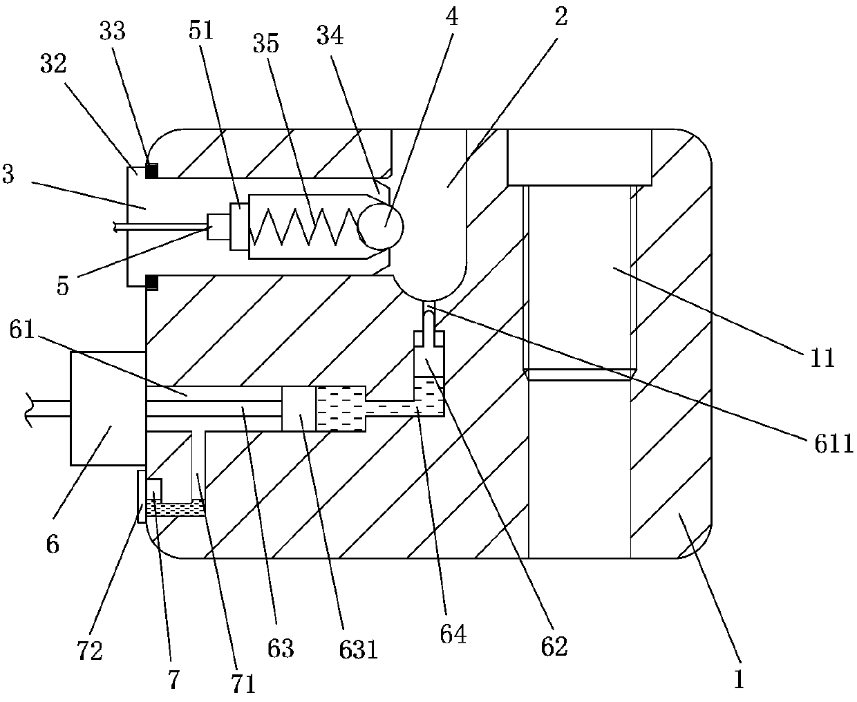
[0014] Below in conjunction with accompanying drawing and specific embodiment the present invention will be described in further detail: Figure 1 to Figure 3 As shown, an injection mold includes an insert installation part 1. The insert installation part 1 is provided with a threaded hole 11 and is installed on the mold by a threaded connection. The insert installation part 1 is provided with an insert The mounting groove 2, the insert positioning part 3 is arranged on the side of the insert mounting groove 2, and the insert positioning part 3 is provided with a storage cavity 31, and a limit ball 4 and a spring are arranged in the storage cavity 31 35, the spring 35 bears against the limit ball 4 to make it in a working state, the insert positioning part 3 is provided with a heating body 5, and the heating body 5 heats the thermal conductor 51 and then passes through the spring 35 The heat is transferred to the limit ball 4 so that the limit ball 4 can heat the metal insert ...


PUM


Abstract

The invention discloses an injection mold which comprises an insert mounting part. The insert mounting part is provided with threaded holes and is mounted on the mold through a threaded connection manner. An insert mounting groove is formed in the insert mounting part. An insert locating part is arranged on the side edge of the insert mounting groove. A containing cavity is formed in the insert locating part. A limiting ball and a spring are arranged in the containing cavity. The spring abuts against the limiting ball so that the limiting ball can be in a working state. A heating body is arranged in the insert locating part. A prospect hole is formed in the bottom of the insert mounting groove. A hydraulic oil cavity is formed in the insert mounting part. The prospect hole is connected with the hydraulic oil cavity. An ejection block and a piston block are arranged in the hydraulic oil cavity. An ejection rod is arranged on the ejection block. The ejection rod can stretch out of the prospect hole, and therefore a metal insert is jacked up. The piston block is connected with a push rod, the push rod is driven by a motor to work, and therefore the piston block is driven to move. Compared with the prior art, according to the injection mold, the metal insert can be stably limited at a preset position, and the situation that the metal insert is separated, and consequently accidents happen is avoided.

Description

technical field [0001] The invention belongs to the field of injection molding machine mold equipment, and in particular relates to an injection mold. Background technique [0002] Plastic products with inserts are widely used at present. It solves the problem that ordinary plastic parts cannot satisfy the mechanical properties, and improves the strength of plastic parts, especially in transmission. When designing molds for plastic products with inserts, it is important to consider how to ensure safe and reliable setting of inserts and efficient and stable production. [0003] as attached figure 1 As shown, the part is a plastic product with an insert, which is widely used, mainly for transmission. The plastic material for this part is ABS, with a metal shaft insert in an elongated shape resembling a worm. When designing the mold for this part, special consideration was required for the fixation of the metal insert and the deformation control of the slender rod. [0004]...

Claims


Application Information

Patent Timeline
Patent Type & Authority Patents(China)
IPC IPC(8): B29C45/26B29C45/14B29C45/72B29C33/12
CPCB29C33/12B29C45/14065B29C45/2602B29C45/7207B29C2045/14163
Inventor 邵谊增
Owner ZHEJIANG BUSINESS TECH INST
Learn More