Automatic charging device for electric vehicle and control method thereof

An automatic charging device and electric vehicle technology, applied in the direction of electric vehicle charging technology, electric vehicles, charging stations, etc., can solve the problems of cumbersome operation, low efficiency, and inability to realize automatic charging, and achieve the effect of improving efficiency

Pending Publication Date: 2017-08-11
福州工大联合新材料有限公司
View PDF14 Cites 11 Cited by
  • Summary
  • Abstract
  • Description
  • Claims
  • Application Information

AI Technical Summary

Problems solved by technology

This method has problems such as requiring manual participation and low efficiency
In ordinary charging stations, although it is possible to manually insert the charging head and the charging port, automatic charging cannot be realized, and there are problems such as cumbersome operation and poor human-machine experience.
In addition, in some special charging scenarios, such as when it is necessary to charge electric vehicles parked in a three-dimensional garage, in the fully automatic lifting three-dimensional garage with a height of tens of meters, there is no room for manual loading and unloading of new energy electric vehicle charging operations. channel, the charging method of manually inserting the charging head and the charging port is obviously not feasible

Method used


Image

  • Automatic charging device for electric vehicle and control method thereof
  • Automatic charging device for electric vehicle and control method thereof
  • Automatic charging device for electric vehicle and control method thereof

Examples


Embodiment Construction

[0034] The present invention will be further described below in conjunction with the accompanying drawings and specific embodiments.

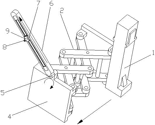
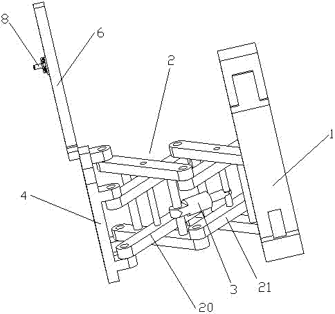
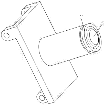
[0035] Such as Figure 1~3 As shown, an electric vehicle automatic charging device in this embodiment includes a horizontally telescopic mechanism platform 2, a charging pile 1 and a support plate 4 arranged on the mechanism platform 2, the support plate 4 is vertically arranged, and the The upper end of the support plate 4 is also provided with a rotating arm 5, a sliding guide rail 6 is fixedly connected to the rotating arm 5, a slider 7 is slidably arranged on the sliding guide rail 6, and a charging head 8 is fixedly connected to the slider 7 and an image acquisition unit, the charging head 8 is electrically connected to the charging pile 1, and the charging head 8 is matched with the charging port of the electric vehicle, and the support plate 4 is set on the mechanism platform 2 through a hydraulic drive rod 3 driving towards the chargin...


PUM


Abstract

The invention relates to an automatic charging device for an electric vehicle and a control method thereof. The automatic charging device comprises a horizontally retractable mechanism platform, a charging pile which is arranged on the mechanism platform and a support plate, the support plate is vertically arranged, the upper end of the support plate is further provided with a rotating arm, the rotating arm is fixedly connected with a sliding guide rail, the sliding guide rail is provided with a sliding block, the sliding block is fixedly connected with a charging head and an image acquisition unit, the charging head is electrically connected with the charging pile and is matched with a charging port of the electric vehicle, the support plate is driven by a hydraulic driving rod which is arranged on the mechanism platform to get close to the charging port, and the charging pile, the image acquisition unit, the sliding guide rail and the hydraulic driving rod are controlled by a control unit. The automatic charging device for the electric vehicle and the control method thereof have the advantages that the position of the charging port is obtained through the image acquisition unit, the charging head is automatically aligned with the charging port, and automatic charging is achieved.

Description

technical field [0001] The invention relates to the field of electric vehicle charging, in particular to an electric vehicle automatic charging device and a control method thereof. Background technique [0002] Electric vehicles (BEV) refer to vehicles powered by vehicle-mounted power supplies, driven by motors to drive wheels, and meeting the requirements of road traffic and safety regulations. Because they have less impact on the environment than traditional vehicles, their prospects are widely optimistic. Electricity is the main source of energy for electric vehicles. At present, when an electric vehicle needs to be charged, charging is mostly realized by manually plugging the charging head and the charging port. This method has the problems of requiring manual participation and low efficiency. In ordinary charging stations, although it is possible to manually plug in the charging head and the charging port, automatic charging cannot be realized, and there are problems ...

Claims


Application Information

Patent Timeline
Patent Type & Authority Applications(China)
IPC IPC(8): B60L11/18
CPCB60L53/16B60L53/30B60L53/31B60L53/37Y02T10/70Y02T90/12Y02T10/7072Y02T90/14
Inventor 罗堪蔡志鹏陈冠豪俞荣贵都可钦
Owner 福州工大联合新材料有限公司
Why Eureka
Try Eureka