Wireless automatic charging method of automobile

A technology of automatic charging and wireless charging, which is applied in the direction of electric vehicle charging technology, charging stations, electric vehicles, etc., can solve the problems of inconvenient power receiving devices for charging devices, occupying land resources, and limited number of cars, so as to save precious time and save Land resources, the effect of solving charging difficulties

Inactive Publication Date: 2016-04-06
郑银雁
View PDF0 Cites 11 Cited by
  • Summary
  • Abstract
  • Description
  • Claims
  • Application Information

AI Technical Summary

Problems solved by technology

At present, the charging places of electric vehicles are mostly planar structures, the number of vehicles that can be charged at the same time is very limited, and the wired charging process requires manual intervention, and it is very inconvenient to align the charging device and the receiving device for wireless charging
The charging process not only needs to occupy a lot of valuable land resources, but also wastes extra valuable time of the car owner, which seriously restricts the development of electric vehicles

Method used


Image

  • Wireless automatic charging method of automobile
  • Wireless automatic charging method of automobile
  • Wireless automatic charging method of automobile

Examples


Embodiment 1

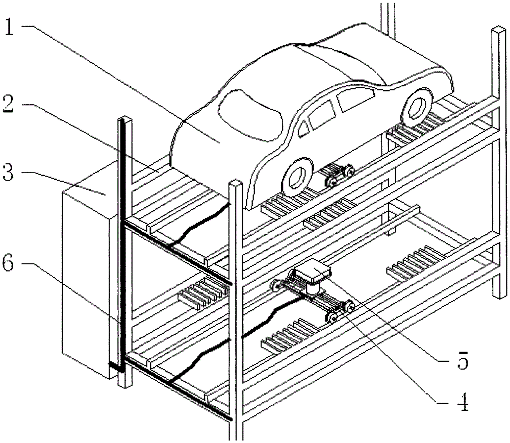
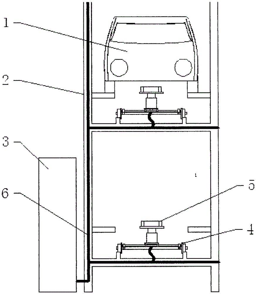
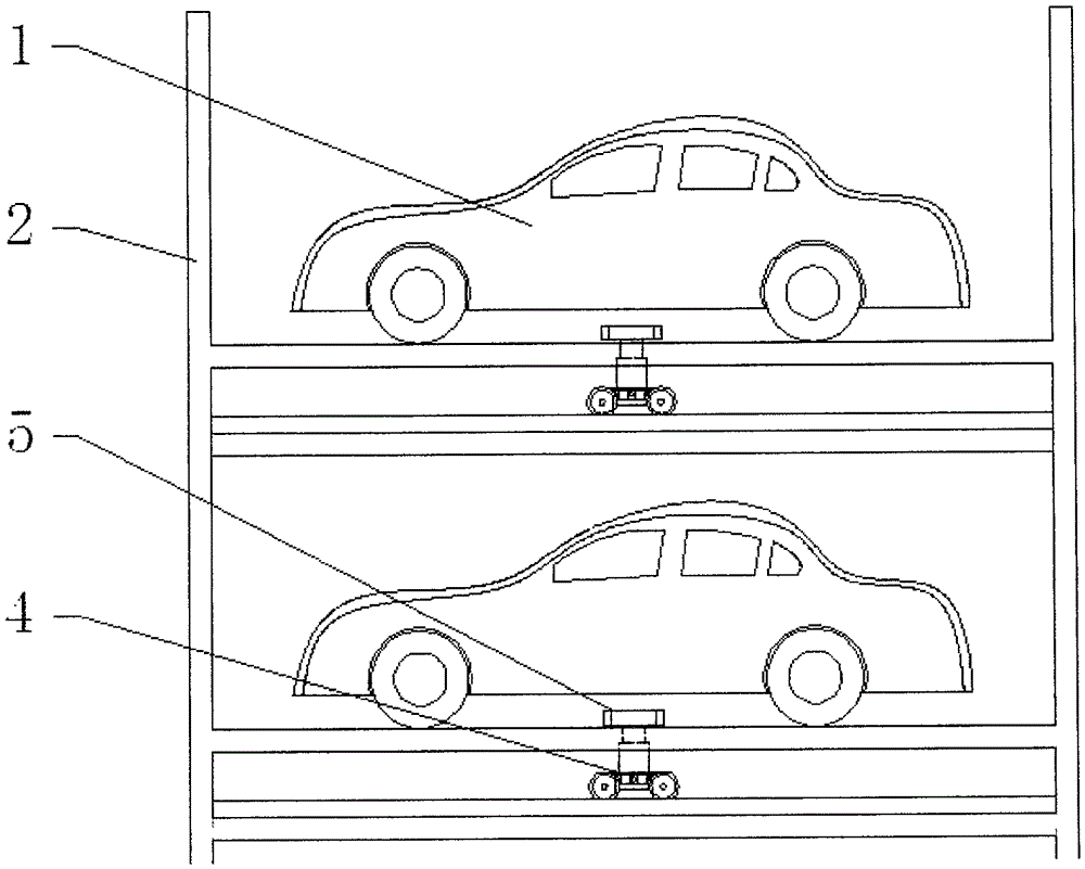
[0026] The structure of a kind of embodiment 1 of the present invention is as Figure 4 to Figure 7 As shown, the supporting platform assembly 4 is an XYZ three-axis structure, including an X-axis moving platform 402, a Y-axis moving platform 401, and a Z-axis lifting platform 403. Driven by the control system, the supporting platform assembly 4 can move along the X and Y directions, and can Lifting along the Z-axis direction drives the wireless charging device 5 on the supporting platform assembly 4 to move along the X, Y, and Z directions.

[0027] After the control system receives the charging command, the first step is to drive the supporting platform assembly 4 and the wireless charging device 5 to move on the XY plane at the bottom of the car 1 to be charged according to the trajectory set by the program, and to detect the position of the car 1 to be charged in the parking space unit 2. The position of the power receiving device; the second step, when the position of the...

Embodiment 2

[0030] The only difference between this embodiment and Embodiment 1 is that the supporting platform assembly 4, the structure of this embodiment is as follows Figure 8 to Figure 11 As shown, the support platform assembly 4 is a mechanical arm structure, including an arm 413 that rotates around a shaft 414, an arm 411 that rotates around a shaft 412, and a Z-axis lifting platform 403. The control system drives the arm 413 and the arm 411 around the shaft 414 and The axis 412 rotates, so that the Z-axis lifting platform 403 and the wireless charging device 5 can move on the XY plane at the bottom of the car 1 to be charged according to the trajectory set by the program, and detect the position of the power receiving device of the car 1 to be charged in the parking space unit 2 .

[0031] This embodiment is driven by a motor or a hydraulic cylinder, and is especially suitable for a three-dimensional garage.

Embodiment 3

[0033] The only difference between this embodiment and Embodiment 1 is that the supporting platform assembly 4, the structure of this embodiment is as follows Figure 12 to Figure 14 As shown, the supporting platform assembly 4 is an intelligent mobile robot structure, including an intelligent robot 422 with universal wheels 423 and a platform 421 that can be lifted along the Z axis. Driven by the control system, the intelligent mobile robot 422 can follow the trajectory set by the program. The bottom of the car to be charged moves on the XY plane to detect the position of the power receiving device of the car to be charged 1 in the parking space unit 2 .

[0034] This embodiment is driven by a motor or a hydraulic cylinder, and is especially suitable for flat places such as charging stations and common garages.


PUM


Abstract

The invention discloses a wireless automatic method of an automobile. The wireless automatic method involves an automobile to be charged, a parking space unit, a wireless charging device, a support platform assembly, a power supply and a control system, wherein the wireless charging device is arranged on the support platform assembly, and the control system is used for driving the support platform assembly and the wireless charging device to move at the bottom of the automobile in the parking space unit before charging, detecting the position of a powered device of the automobile to be charged, moving the wireless charging device to an appropriate charging position and then beginning to charge. The invention provides a method for wireless automatic charging of the automobile parked in a garage, manual intervention is not needed, and the method is convenient and high-efficiency, is particularly used for a three-dimensional garage and a charging station, and is also suitably used for normal ground parking places.

Description

technical field [0001] The invention relates to a method for wireless automatic charging of automobiles, in particular to a method for wireless automatic charging of automobiles in three-dimensional garages and charging stations. Background technique [0002] As the number of electric vehicles in my country continues to increase, the problem of charging difficulties has become increasingly prominent. At present, the charging places of electric vehicles are mostly planar structures, and the number of vehicles that can be charged at the same time is very limited, and the wired charging process requires manual intervention, and it is very inconvenient to align the charging device and the receiving device for wireless charging. The charging process not only needs to occupy a lot of valuable land resources, but also wastes extra valuable time of car owners, which seriously restricts the development of electric vehicles. Contents of the invention [0003] In order to overcome t...

Claims


Application Information

Patent Timeline
Patent Type & Authority Applications(China)
IPC IPC(8): H02J7/00H02J50/90
CPCB60L53/12B60L53/38Y02T10/70Y02T10/7072Y02T90/12Y02T90/14
Inventor 郑银雁
Owner 郑银雁
Why Eureka
Try Eureka