Supercharge Your Innovation With Domain-Expert AI Agents!

Angle of Arrival Estimation

A technology of angle of arrival and plane of incidence, applied in the field of radar systems, can solve problems such as phase ambiguity, aperture size limitation, and increased antenna cost

Active Publication Date: 2021-03-12
GM GLOBAL TECH OPERATIONS LLC
View PDF3 Cites 0 Cited by
  • Summary
  • Abstract
  • Description
  • Claims
  • Application Information

AI Technical Summary

Problems solved by technology

High angular resolution requires a large aperture and a large number of antenna elements, which increases the cost of the antenna
In addition, the size of the aperture and the number of elements are limited by the spacing of the antenna elements due to phase ambiguity

Method used


Image

  • Angle of Arrival Estimation
  • Angle of Arrival Estimation
  • Angle of Arrival Estimation

Examples


Embodiment Construction

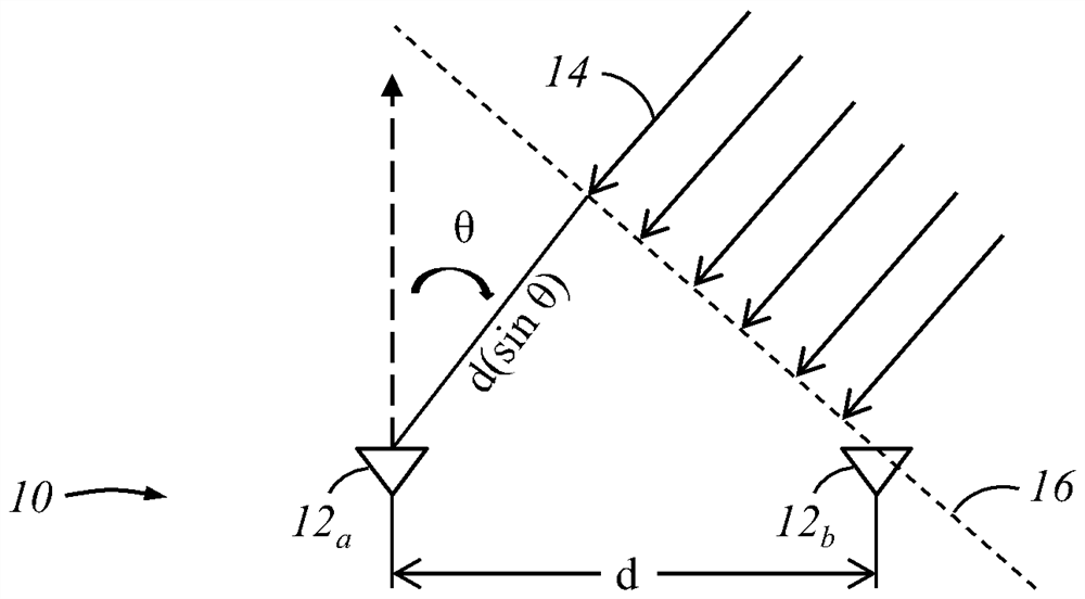
[0051] The systems and methods described below relate to resolving phase ambiguities associated with antenna arrays when determining the angle of arrival of an incident plane wave. The method includes measuring the phase difference between signals received at each antenna channel to generate a set of possible angles of arrival based on the phase ambiguity. These ambiguities are compared to estimated angles of arrival based on time-of-arrival measurements obtained from each antenna channel. Ambiguity is resolved by selecting from the set of possible arrival angles the angle of arrival having the smallest absolute difference in relative estimated time of arrival.

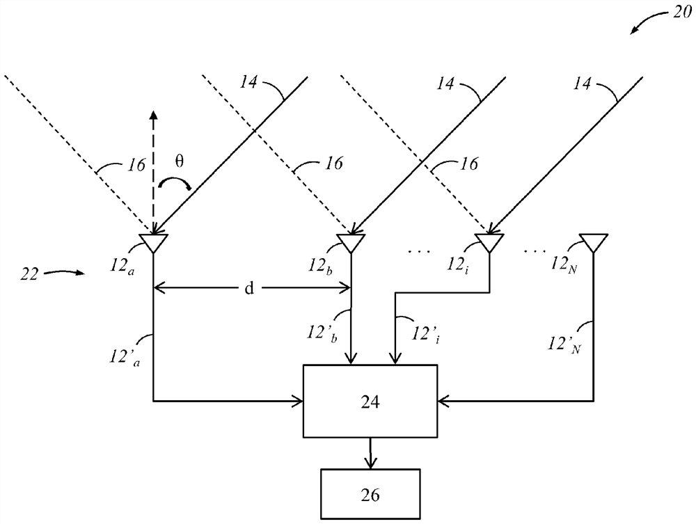
[0052] figure 2 An exemplary radar detection system 20 that can be used to implement the methods disclosed herein is illustrated. The radar detection system 20 includes a linear antenna array 22 having N evenly spaced antenna elements 12 separated by a distance d a-N . The angle of arrival of the input incident s...


PUM


Abstract

The present invention relates to angle of arrival estimation and discloses a method for determining the angle of arrival of an incident plane wave received by an antenna array. The method includes receiving signals from a plurality of antenna receive channels, determining a set of possible angles of arrival of an incident plane wave based on signals received at the plurality of receive channels, measuring pulses of the incident plane wave between signals received at the plurality of receive channels delay, and calculating the angle of arrival of the incident plane wave based on the set of possible angles of arrival and the measured pulse delay.

Description

[0001] This application claims the benefit of US Provisional Patent Application Serial No. 62 / 281,822, filed January 22, 2016, the entire contents of which are hereby incorporated by reference. technical field [0002] The present invention relates generally to radar systems and, more particularly, to estimation of angle of arrival in antenna arrays having widely spaced elements. Background technique [0003] Radar is an object detection system that uses radio waves transmitted and received by antennas to determine the range, angle and / or velocity of objects. In most modern systems, radar employs an array antenna consisting of multiple antenna elements arranged and interconnected to form a single antenna. In operation, the phase difference between signals received by the antenna elements is measured and used to establish the signal direction of arrival. For example, if the antenna elements are located on a planar surface, and if the signal arrives perpendicular to the surfa...

Claims


Application Information

Patent Timeline
Patent Type & Authority Patents(China)
IPC IPC(8): G01S3/14
CPCG01S3/14G01S3/48G01S7/03G01S13/42G01S3/50
Inventor O.比亚勒I.比利克
Owner GM GLOBAL TECH OPERATIONS LLC
Features
  • R&D
  • Intellectual Property
  • Life Sciences
  • Materials
  • Tech Scout
  • Unparalleled Data Quality
  • Higher Quality Content
  • 60% Fewer Hallucinations
Learn More