Electronic door lock and door with automatic charging device

An automatic charging device and electronic door lock technology, applied in the field of locks, can solve the problems of accurate grasp, the electronic door lock cannot be automatically charged and cannot be charged, etc.

Active Publication Date: 2019-07-05
GUIZHOU UNIVERSITY OF FINANCE AND ECONOMICS
View PDF6 Cites 0 Cited by
  • Summary
  • Abstract
  • Description
  • Claims
  • Application Information

AI Technical Summary

Problems solved by technology

[0005] The purpose of the present invention is to provide an electronic door lock and door with an automatic charging device, so as to alleviate the technical problems existing in the prior art that the electronic door lock cannot be automatically charged or cannot accurately grasp the charging state

Method used


Image

  • Electronic door lock and door with automatic charging device
  • Electronic door lock and door with automatic charging device
  • Electronic door lock and door with automatic charging device

Examples


Embodiment 1

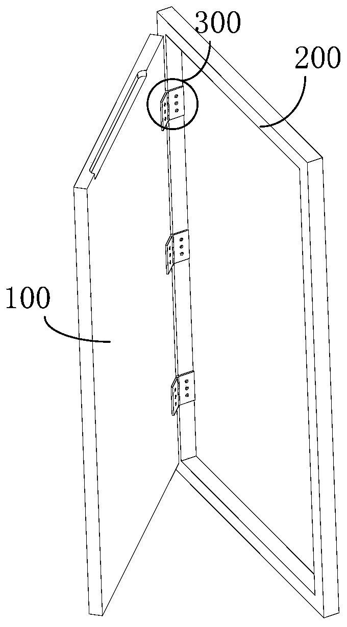
[0040] This embodiment provides an electronic door lock with an automatic charging device, including a transmission device 300, a power generation device, a power storage device, a battery, a control device and a voltage detection device.

[0041] in,

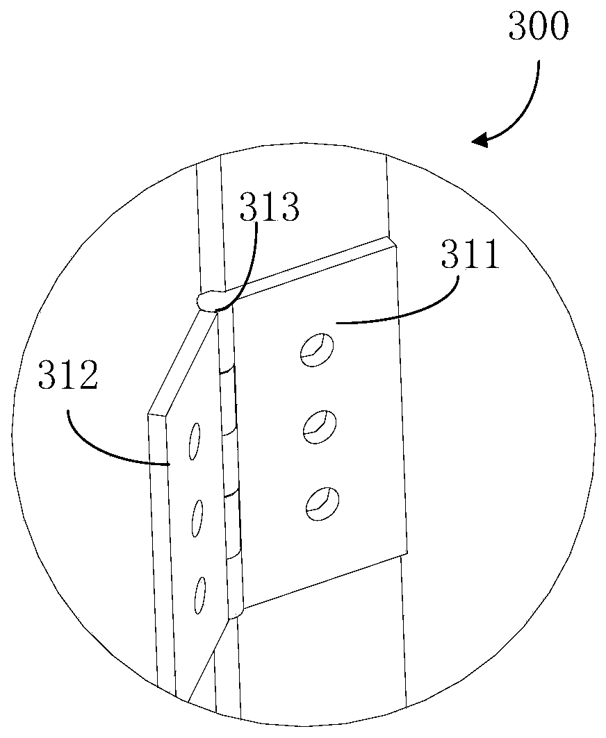
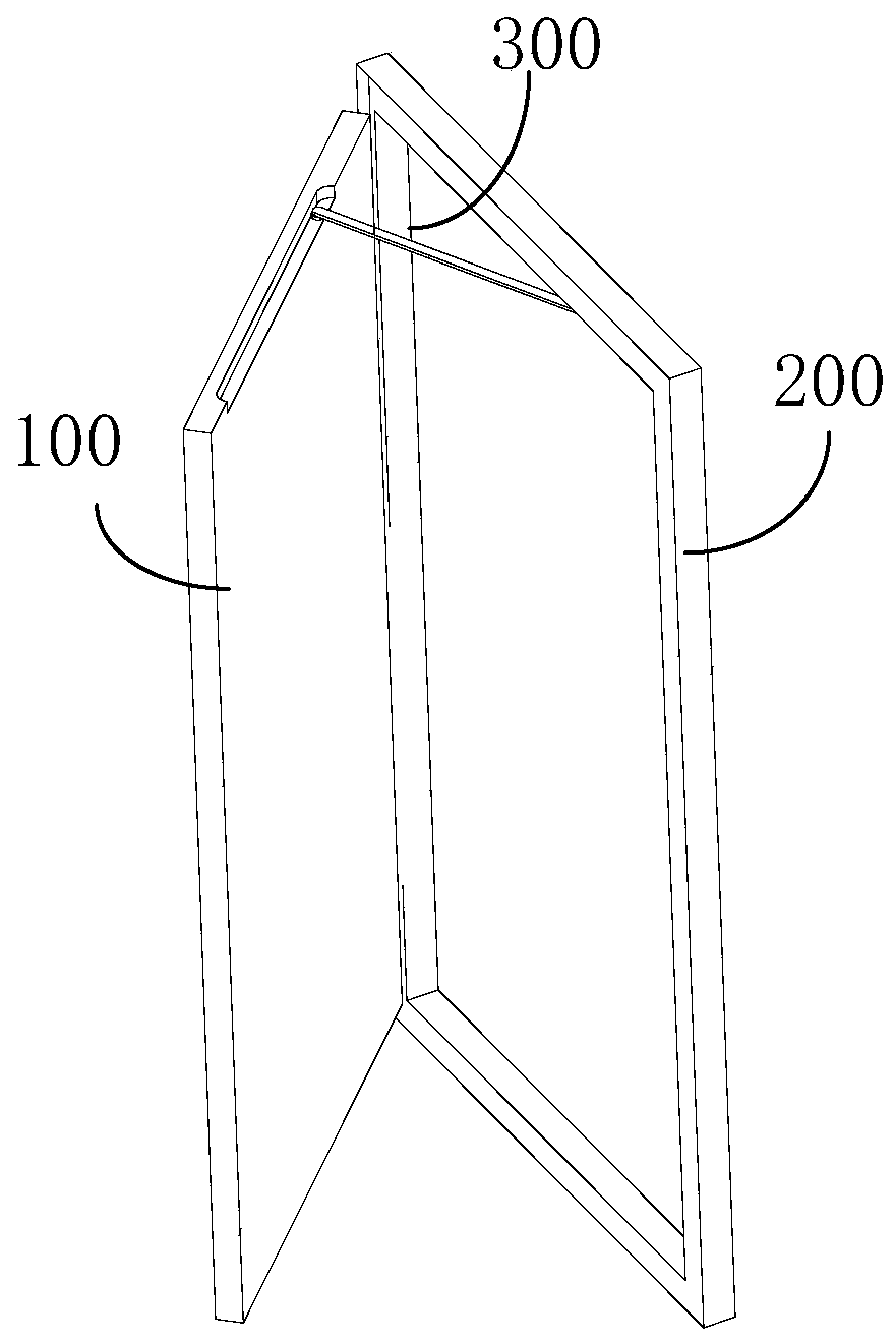
[0042] The transmission device 300 is arranged between the door body 100 and the door frame 200, and the power generation device is arranged on the door body 100 or the door frame 200, and is respectively connected with the transmission device 300 and the power storage device; power storage device, battery, control device and voltage detection device Set in the electronic door lock and electrically connected in turn;

[0043]The transmission device 300 is used to transmit the interaction force between the door body 100 and the door frame 200 to the power generation device, and the power generation device converts the interaction force into electric energy and transmits it to the power storage device;

[0044] The voltage detec...

Embodiment 2

[0065] This embodiment provides a door, including the electronic door lock with a self-charging device in Embodiment 1. In order to save space, the technical solution mentioned in Embodiment 1 will not be repeated here.

[0066] It should be emphasized that:

[0067] It can be seen from Embodiment 1 that during the opening and closing process of the door, the door body 100 rotates relative to the door frame 200, and since the transmission device 300 is arranged between the door body 100 and the door frame 200, the rotation generated by the rotation motion of the door body 100 The torque can be transmitted to the power generation device through the transmission device 300, and the electric energy generated by the power generation device is transmitted to and stored in the power storage device, and the power storage device charges the battery according to different working states of the battery. More specifically, when the voltage value of the battery detected by the voltage de...


PUM


Abstract

The invention relates to the technical field of locks, in particular to an electronic door lock with an automatic charging device and a door. The technical problem that in the prior art, an electronic door lock cannot be charged or the charging state cannot be grasped accurately is relieved. The electronic door lock comprises a transmission device, a power generating device, a power storage device, a battery, a control device and a voltage detecting device. When the voltage value is smaller than or equal to a first preset voltage threshold value, the control device controls the power storage device to charge the battery; and when the voltage value is larger than or equal to a second preset voltage threshold value, the control device controls the power storage device to stop charging the battery. The voltage detecting module detects the battery voltage, and the control module controls whether the power storage device conducts the charging or discharging work mode or not, so that the electronic door lock can be charged, and the charging state of the electronic door lock can be controlled accurately and efficiently.

Description

technical field [0001] The invention relates to the technical field of locks, in particular to an electronic door lock and a door with an automatic charging device. Background technique [0002] Electronic door locks have the characteristics of a large number of keys that can be accommodated and a high security index, and are widely used in housing, hotels and other environments. Electronic door locks need to consume electricity to maintain their normal operation. In response to the national call for energy conservation and environmental protection, electronic door locks are developing in the direction of energy conservation and environmental protection. For example, electronic door locks using button batteries have been developed, but button batteries can only maintain the control part. Working, driving the electromagnet or brake motor requires more power to ensure its normal operation, so the electronic door lock needs to change the battery frequently to make the door lock...

Claims


Application Information

Patent Timeline
Patent Type & Authority Patents(China)
IPC IPC(8): E05B47/00F03G7/00H02J7/32
CPCE05B47/00E05B2047/0058E05B2047/0062E05B2047/0097F03G7/00H02J7/32
Inventor 夏换蔡绍洪于小民李爽
Owner GUIZHOU UNIVERSITY OF FINANCE AND ECONOMICS
Why Eureka
Try Eureka