Lifting device for current collector

A lifting device and current collector technology, applied in the field of current collectors, can solve problems such as failure to meet the requirements of lifting shoes, and achieve the effect of meeting the requirements of lifting shoes

Inactive Publication Date: 2017-08-18
ZHUZHOU ELECTRIC LOCOMOTIVE CO
View PDF10 Cites 8 Cited by
  • Summary
  • Abstract
  • Description
  • Claims
  • Application Information

AI Technical Summary

Problems solved by technology

[0002] At present, under the action of the spring force, the current collectors for maglev trains use a four-bar linkage mechanism to lift

Method used


Image

  • Lifting device for current collector
  • Lifting device for current collector
  • Lifting device for current collector

Examples


Embodiment Construction

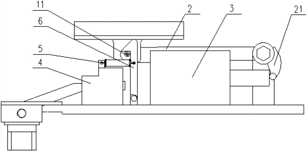
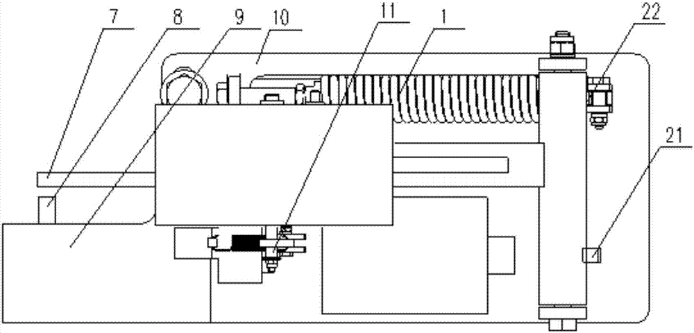
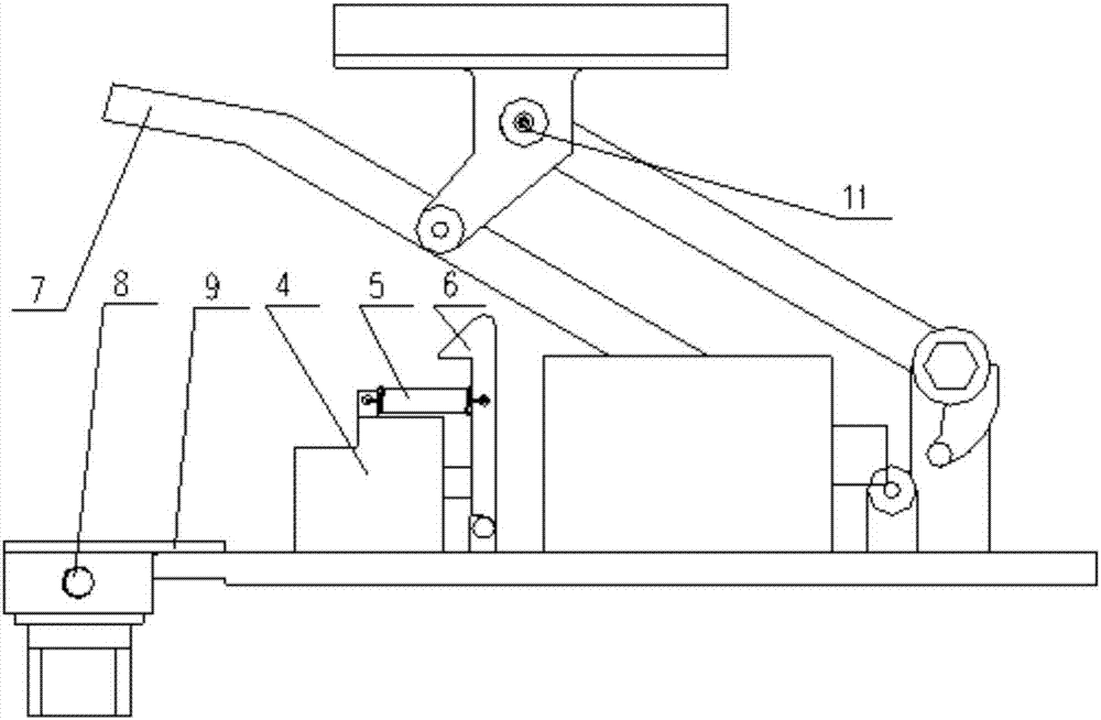
[0034] The embodiment of the present invention provides a lifting device for the current collector, which realizes the lifting and lowering of the shoe for the current collector.

[0035] In order to make the objectives, technical solutions, and advantages of the embodiments of the present invention clearer, the technical solutions in the embodiments of the present invention will be described clearly and completely in conjunction with the accompanying drawings in the embodiments of the present invention. Obviously, the described embodiments It is a part of the embodiments of the present invention, not all the embodiments. Based on the embodiments of the present invention, all other embodiments obtained by those of ordinary skill in the art without creative work shall fall within the protection scope of the present invention.

[0036] The lifting device for the current collector provided by the embodiment of the present invention includes a bottom plate 10; a four-bar linkage mechan...


PUM


Abstract

The invention provides a lifting device for a current collector, comprising a bottom plate, a four bar linkage mechanism, a first driving part, a first elastic part, a limiting part, a second elastic part and a second driving part, wherein the four bar linkage mechanism is capable of driving the current collector to ascend and descend, and a frame of the four bar linkage mechanism is arranged on the bottom plate; the first driving part is capable of driving a crank of the four bar linkage mechanism to rotate to the descending direction; the first elastic part has the elastic force of driving the crank to rotate to the ascending direction, one end of the first elastic part is arranged on the bottom plate, and the other end of the first elastic part is connected with the crank; the limiting part is capable of limiting the four bar linkage mechanism in the descending position; the second elastic part has the elastic force of locking the four bar linkage mechanism in the limiting part, one end of the second elastic part is fixed, and the other end of the second elastic part is connected with the limiting part; and the second driving part is capable of driving the limiting part to release the four bar linkage mechanism. According to the invention, the first driving part, the second driving part, the first elastic part, the second elastic part and the limiting part are matched to enable the four bar linkage mechanism to ascend and descend, so as to enable the current collector to ascend and descend, thereby meeting the ascending and descending requirements of electrical equipment.

Description

Technical field [0001] The present invention relates to the technical field of current collectors, and more specifically, to a lifting device for current collectors. Background technique [0002] At present, under the action of spring force, the current receiver for magnetic levitation trains adopts a four-bar linkage mechanism to realize the lifting of the current receiver, which cannot meet the requirements of lowering shoes when the main circuit needs to be isolated in some cases. [0003] In summary, how to implement lifting and lowering of the shoe on the current collector is currently an urgent technical problem to be solved by those skilled in the art. Summary of the invention [0004] In view of this, the object of the present invention is to provide a lifting device for the current collector, so as to realize the lifting and lowering of the shoe for the current collector. [0005] In order to achieve the above objective, the present invention provides the following technical...

Claims


Application Information

Patent Timeline
IPC IPC(8): B60L5/30
CPCB60L5/30B60L2200/26
Inventor 张海丰张彦林陈明国彭宝林周洁郭瑾玉陈敏坚李军孙宁王秋红
Owner ZHUZHOU ELECTRIC LOCOMOTIVE CO
Why Eureka
Try Eureka