Spring retractable door

A spring type and pull plate technology, which is applied in the direction of door leaves, windows/doors, door/window accessories, etc., can solve problems such as the inability to open the door and affect escape

Active Publication Date: 2018-05-25
新田诚美门窗有限责任公司
View PDF1 Cites 0 Cited by
  • Summary
  • Abstract
  • Description
  • Claims
  • Application Information

AI Technical Summary

Problems solved by technology

[0004] The purpose of the present invention is to provide a tension spring type retractable door to solve the problem in the prior art that the door cannot be opened after a fire, which affects escape in the event of a disaster

Method used


Image

  • Spring retractable door
  • Spring retractable door

Examples


Embodiment Construction

[0015] The present invention will be described in further detail below by means of specific embodiments:

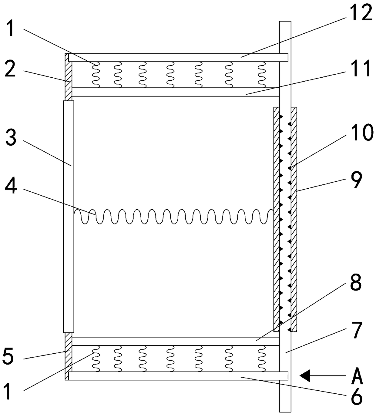
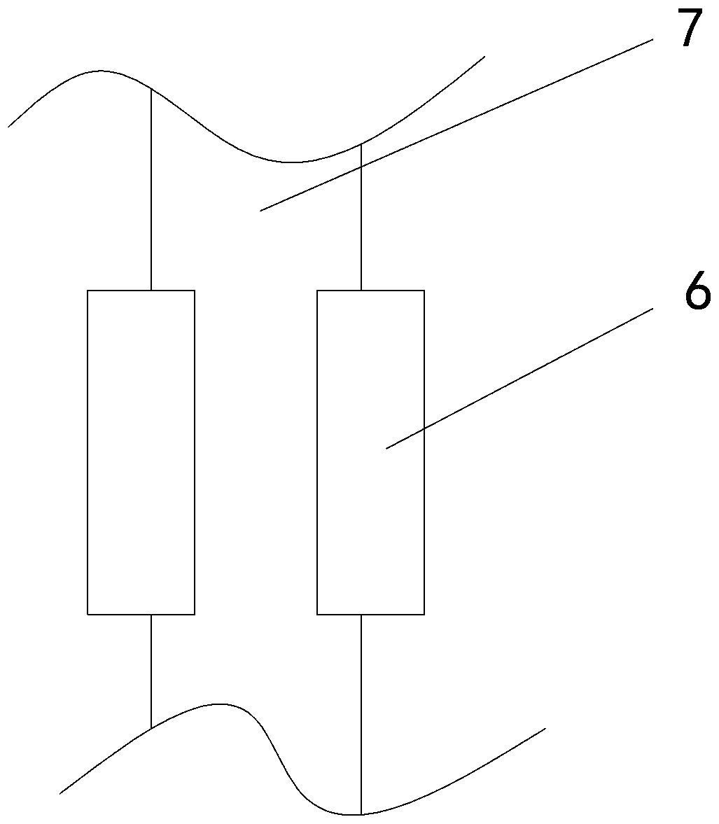
[0016] The reference signs in the accompanying drawings of the specification include: the first tension spring 1, the first contact piece 2, the door post 3, the second tension spring 4, the second contact piece 5, the fourth pull plate 6, the door shaft 7, the third Pulling plate 8, heat insulation cover 9, coolant 10, second pulling plate 11, first pulling plate 12.

[0017] Embodiment: The extension spring type retractable door in this scheme includes a door post 3, a door shaft 7, a first pull plate 12, a second pull plate 11, a third pull plate 8 and a fourth pull plate 6, the first pull plate The plate 12 is equal to the fourth pull plate 6, the second pull plate 11 is equal to the third pull plate 8, the second pull plate 11 and the third pull plate 8 are located between the door post 3 and the door shaft 7, and the second pull plate 11 and the third pull plate 8 a...


PUM


Abstract

The invention belongs to the field of doors of special purposes and particularly discloses a tension spring type inward retraction door. The tension spring type inward retraction door comprises a first pulling plate, a second pulling plate, a third pulling plate and a fourth pulling plate which are of the same length. One end of the second pulling plate and one end of the third pulling plate are perpendicularly fixed to the upper portion and the lower portion of a door shaft correspondingly. The upper end and the lower end of a door column are separately in transition fit with a first contact part and a second contact part which are made from scandium fluoride. One end of the first pulling plate is stored on the first contact part, and the other end of the first pulling plate is in slide fit with the door shaft. The first contact part is stored at one end of the fourth pulling plate, and the other end of the fourth pulling plate is in slide fit with the door shaft. First tension springs at a tensional state are separately arranged between the first pulling plate and the second pulling plate as well as between the third pulling plate and the fourth pulling plate. A second tension spring at a tensional state is arranged between the door column and the door shaft. By adoption of the scheme, a frame of the door automatically becomes smaller along with rising of the temperature, and therefore the problem the in the prior art, a room door cannot be opened after ignition, and therefore the escape function of the door under the disaster condition is affected is solved.

Description

technical field [0001] The present invention is in the field of special purpose doors. Background technique [0002] The existing anti-theft door is deformed due to heat or force extrusion, and the door cannot be opened, especially in the case of a disaster, it is impossible to escape. Therefore, there is a need for a door structure with a retractable four-bar structure as the main body, so that when the door is under pressure, the two opposite sides can shrink in the same direction, avoiding the problem that the door cannot be opened. At the same time, considering the situation of heat exposure, plastic connectors are added, so that the door can ensure the escape function in case of disaster. [0003] The patent document whose authorized announcement is CN103899223B discloses a retractable anti-theft door, including a bolt support rod, a concave four-bar linkage mechanism, a sleeve, an inner door frame support telescopic rod, a horizontal connecting strip, and a longitudin...

Claims


Application Information

Patent Timeline
Patent Type & Authority Patents(China)
IPC IPC(8): E06B3/72E05D7/00E05D11/00E05D5/14
CPCE05D5/14E05D7/00E05D11/00E06B3/72E06B2003/7059E06B2003/7092
Inventor 周维
Owner 新田诚美门窗有限责任公司
Why Eureka
Try Eureka