Escape device for tunnel fire disaster

An escape device and fire technology, which can be applied to visible signal devices, mine/tunnel ventilation, signal devices, etc., and can solve problems such as threatening people's lives, health and safety, inhaling a lot of smoke, etc.

Pending Publication Date: 2022-04-26
HEBEI UNIV OF TECH
View PDF0 Cites 0 Cited by
  • Summary
  • Abstract
  • Description
  • Claims
  • Application Information

AI Technical Summary

Problems solved by technology

[0003] As a relatively closed structure, the high-temperature dense smoke in the tunnel seriously threatens people's life, health and safety. Usually only one fire door is set in front of the escape route, causing people to inhale a large amount of dense smoke during the escape process

Method used


Image

  • Escape device for tunnel fire disaster
  • Escape device for tunnel fire disaster
  • Escape device for tunnel fire disaster

Examples


Embodiment 1

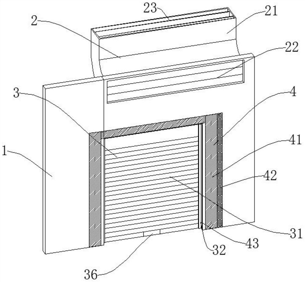
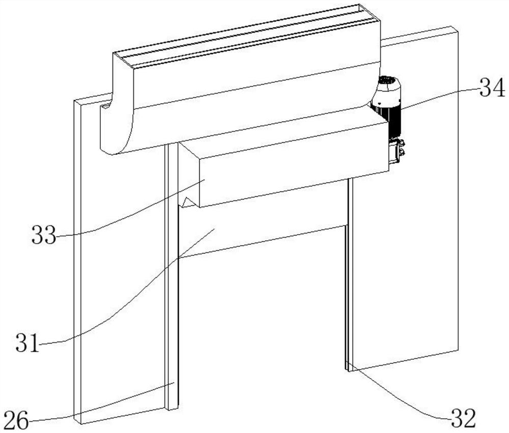
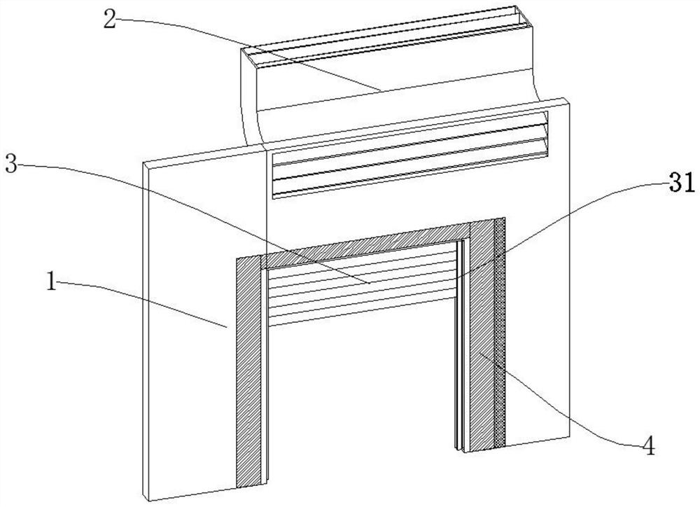
[0048] Such as Figure 1-7As shown, an escape device for tunnel fire disasters, including a one-way smoke exhaust mechanism 2 and a sealing mechanism 3 for preventing the intrusion of dense smoke, a firewall 1 for fixed installation, and an adjustment mechanism 5 for controlling opening and closing And a detection mechanism 4 for detecting the movement of dense smoke. A sealing mechanism 3 is installed on the firewall 1. A one-way smoke exhaust mechanism 2 is arranged on the upper side of the sealing mechanism 3. A detection mechanism 4 is arranged on both sides of the front end of the sealing mechanism 3. One-way exhaust An adjustment mechanism 5 is installed on the smoke mechanism 2;

[0049] The one-way smoke exhaust mechanism 2 includes a smoke exhaust pipe 21, an opening and closing plate 22, a one-way plate 23, and a ratchet group 24; an opening and closing plate 22 is arranged between the front end of the smoke exhaust pipe 21 and the firewall 1, and a one-way opening a...

Embodiment 2

[0054] Such as Figure 8 , the difference between this embodiment and embodiment 1 is:

[0055] The adjustment mechanism 5 includes an adjustment motor 51, a passive bevel gear 511, an active bevel gear 512, and a connecting rod 513; the adjustment shaft 25 is connected with a passive bevel gear 511, one end of the passive bevel gear 511 is connected with an active bevel gear 512, and three active bevel gears 512 Connected by connecting rod 513, one end of the lowermost adjustment shaft 25 is connected to the adjusting motor 51. When the angle and opening and closing of the opening and closing plate 22 need to be adjusted, the control and adjusting motor 51 drives the active bevel gear 512 through the connecting rod 513 to cooperate with the passive bevel gear 511 and adjust shaft 25, so that the opening and closing plate 22 can be opened and closed; the passive bevel gear 511 is keyed to the adjustment shaft 25, the passive bevel gear 511 and the driving bevel gear 512 mesh, ...


PUM


Abstract

The invention discloses an escape device for tunnel fire disasters. The escape device comprises a one-way smoke exhaust mechanism, a sealing mechanism, a firewall, an adjusting mechanism and a detection mechanism, wherein the one-way smoke exhaust mechanism and the sealing mechanism are used for preventing dense smoke from invading; the firewall is fixedly mounted; the sealing mechanism is installed on the firewall, the one-way smoke exhaust mechanism is arranged on the upper side of the sealing mechanism, and the detection mechanisms are arranged on the two sides of the front end of the sealing mechanism. By means of the one-way smoke exhaust mechanism, dense smoke in the tunnel can be exhausted in time; by means of the detection mechanism, when a fire occurs and a large amount of dense smoke is generated, an obvious safety channel prompt is arranged at an escape channel, real-time detection is conducted, and water is sprayed in time to form a water mist wall to block the dense smoke; by means of the sealing mechanism, the fireproof rolling shutter door is closed in time to prevent dense smoke from invading the escape channel under the condition of no person and high smoke; through reliable cooperation of all the mechanisms, the problem that high-temperature dense smoke affects personnel escape is effectively solved.

Description

technical field [0001] The invention relates to the field of tunnel fire escape, in particular to an escape device for tunnel fire disasters. Background technique [0002] With the rapid development of my country's transportation industry in recent years, the construction scale of infrastructure such as tunnels and subways has increased significantly. As one of the most common engineering structures, tunnels have many advantages and cannot be ignored due to their narrow and small characteristics. Disadvantages of difficult fire rescue. According to investigations, tunnel fires are extremely prone to tunnel safety accidents. Once a fire occurs, especially in urban subway tunnels with high population density and difficult emergency evacuation, it often causes relatively large casualties and seriously threatens people's property and life safety. . [0003] As a relatively closed structure, the high-temperature dense smoke in the tunnel seriously threatens people's life, health...

Claims


Application Information

Patent Timeline
Patent Type & Authority Applications(China)
IPC IPC(8): E21F11/00E21F17/12E21F1/00E21F1/04E21F1/14E21F5/04E06B9/15E06B9/70G08B5/36
CPCE21F11/00E21F17/12E21F1/003E21F1/04E21F1/145E21F5/04E06B9/15E06B9/70G08B5/36
Inventor 张一鸣侯建戎贤
Owner HEBEI UNIV OF TECH
Why Eureka
Try Eureka