Experiment table embedded waste liquid customized cabinet

A kind of laboratory bench, built-in technology, applied in the direction of laboratory stool/lab bench, laboratory equipment, storage of dangerous substances, etc., can solve problems such as instrument failure, achieve low cost of improvement, increase subjective evaluation of personnel, and ventilate The effect of reducing volume demand

Pending Publication Date: 2018-08-24
通标标准技术服务(青岛)有限公司
View PDF6 Cites 0 Cited by
  • Summary
  • Abstract
  • Description
  • Claims
  • Application Information

AI Technical Summary

Problems solved by technology

At the same time, in order to solve the problem of instrument failure caused by the leakage of waste reagents and the adhesion of escaped reagents to the circuit board of the instrument

Method used


Image

  • Experiment table embedded waste liquid customized cabinet
  • Experiment table embedded waste liquid customized cabinet
  • Experiment table embedded waste liquid customized cabinet

Examples


Embodiment 1

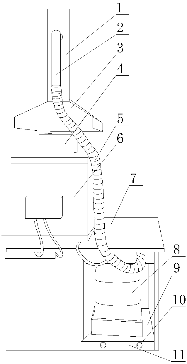
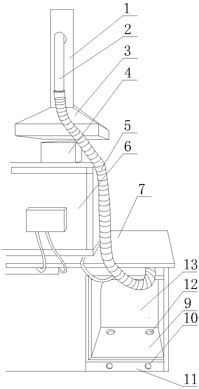
[0031] Such as figure 1 and figure 2 As shown, the built-in waste liquid custom cabinet of the test bench includes the exhaust fan, the test bench, the waste liquid cabinet and the waste liquid barrel in sequence from top to bottom. The exhaust fan includes the main exhaust pipe and the exhaust branch pipe. Cover, the suction hood is set facing the exhaust port of the testing instrument on the test bench, the end of the exhaust branch pipe is connected to one end of the exhaust pipe, and the other end of the exhaust pipe is connected to the exhaust port of the waste liquid cabinet; the waste liquid cabinet is set to The cabinet body and the cabinet door are connected to form a hollow sealed structure. There is a storage cavity under the waste liquid cabinet, and the waste liquid bucket is placed in the storage cavity. The bottom wall of the storage cavity is provided with a load-bearing plate. The bottom walls of the cabinets are spaced apart to form a hollow air duct, the i...

Embodiment 2

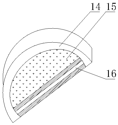
[0041] On the basis of Example 1, different from Example 1, such as image 3 As shown, the inner wall of the suction hood is provided with a detachable adsorption gasket, and the port of the adsorption gasket is provided with a ventilation hole along the width direction, and an adsorption cavity is formed between the adsorption gasket and the ventilation hole, and the adsorption cotton is embedded Set in the adsorption cavity.

[0042] The adsorption gasket is set as a hollow arch bridge arc structure with openings on both sides, and the adsorption cotton is set as a structure whose inner diameter matches the adsorption cavity, and a honeycomb adsorption mesh is opened inside to improve the adsorption effect; Embedded on the inner wall of the suction hood, it is convenient and quick to disassemble and install.

[0043] The specific use process is:

[0044] The airflow discharged from the air outlet on the top of the test bench is directly absorbed into the suction hood. The ...


PUM


Abstract

The invention discloses an experiment table embedded waste liquid customized cabinet. An exhaust fan comprises an exhaust main pipe and an exhaust branch pipe, wherein a suction hood is arranged at the tail end of the exhaust main pipe; the suction hood directly faces an air outlet of a detection instrument of the experiment table; the exhaust branch pipe is connected with an exhaust port of the waste liquid cabinet through an exhaust pipeline; a cavity is formed below the waste liquid cabinet; a waste liquid barrel is put in the cavity; a bearing plate is arranged on the bottom wall of the cavity; hollow air channels are spaced between the bearing plate and the bottom wall of the waste liquid cabinet; a ventilation opening a is formed in the inner side upper surface of the bearing plate;a ventilation opening b is formed in the outer side wall of the hollow air channel; the hollow air channels are communicated with the cavity through the ventilation opening a and the ventilation opening b. Through the exhaust system, the irritant gases volatilizing or escaping from the waste liquid barrel are exhausted. A vortex dead angle is not formed easily, the residual quantity of the escaping irritant gases is small, the demand on the exhaust amount is low, the gas exchange frequency is reduced, the exhaust effect is obvious, and the comfort level in the room is raised, thereby being low-carbon and environmentally friendly.

Description

technical field [0001] The invention belongs to the technical field of instrument analysis equipment, and in particular relates to a built-in waste liquid customized cabinet for a test bench. Background technique [0002] Instrumental analysis is very common in the fields of chemistry, biology, and medicine, and the waste liquid discharge system is an important part of the analytical instrument. At present, the waste liquid discharge system of most instruments is to install a waste liquid discharge pipe at the end of the instrument detection flow path, and then lead the waste liquid to the waste liquid bucket. The waste liquid bucket is directly placed in the indoor open space next to the instrument. This way of entering the waste liquid determines that the waste liquid barrel cannot be completely sealed, which will cause volatiles in the waste liquid, such as strong volatile acids, to escape into the indoor air. Although the laboratory generally has an exhaust system, bec...

Claims


Application Information

Patent Timeline
Patent Type & Authority Applications(China)
IPC IPC(8): B01L9/02B01L1/00B08B15/02
CPCB01L1/50B01L9/02B08B15/02
Inventor 王大章冷田忠王渤徐霞赫秀萍王剑
Owner 通标标准技术服务(青岛)有限公司
Why Eureka
Try Eureka