Lens adjustment module and projection device

A lens and module technology, applied in projection devices, instruments, optics, etc.

Active Publication Date: 2019-09-20
QISDA OPTRONICS (SUZHOU) CO LTD +1
View PDF8 Cites 0 Cited by
  • Summary
  • Abstract
  • Description
  • Claims
  • Application Information

AI Technical Summary

Problems solved by technology

[0005] The object of the present invention is to provide a lens supporting device and a projection device, which can realize that the lens can move as the user operates the drive unit, so as to solve the problem of "empty travel" in the prior art

Method used


Image

  • Lens adjustment module and projection device
  • Lens adjustment module and projection device
  • Lens adjustment module and projection device

Examples


Embodiment Construction

[0025] The following descriptions of the various embodiments refer to the accompanying drawings to illustrate specific embodiments in which the invention may be practiced. The directional terms mentioned in the present invention, such as "up", "down", "front", "rear", "left", "right", "side", etc., only refer to the directions of the attached drawings. Therefore, the directional terms used are for describing and understanding the present invention, not for limiting the present invention.

[0026] In the following embodiments, the same parts are denoted by the same reference numerals in different figures.

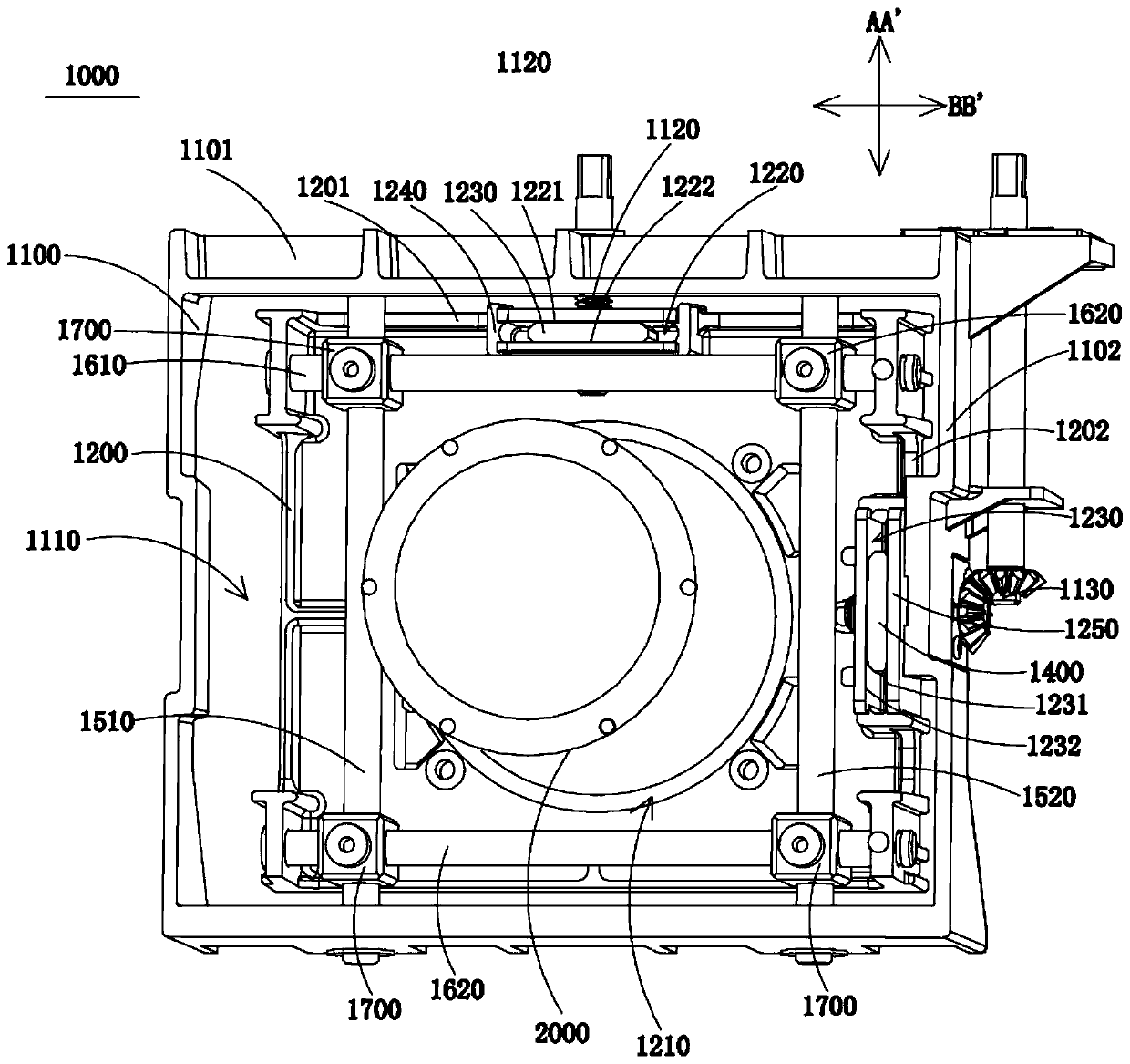
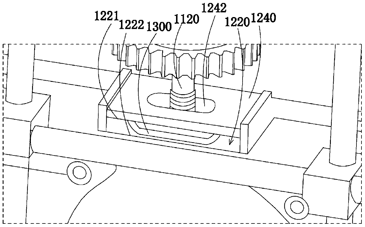
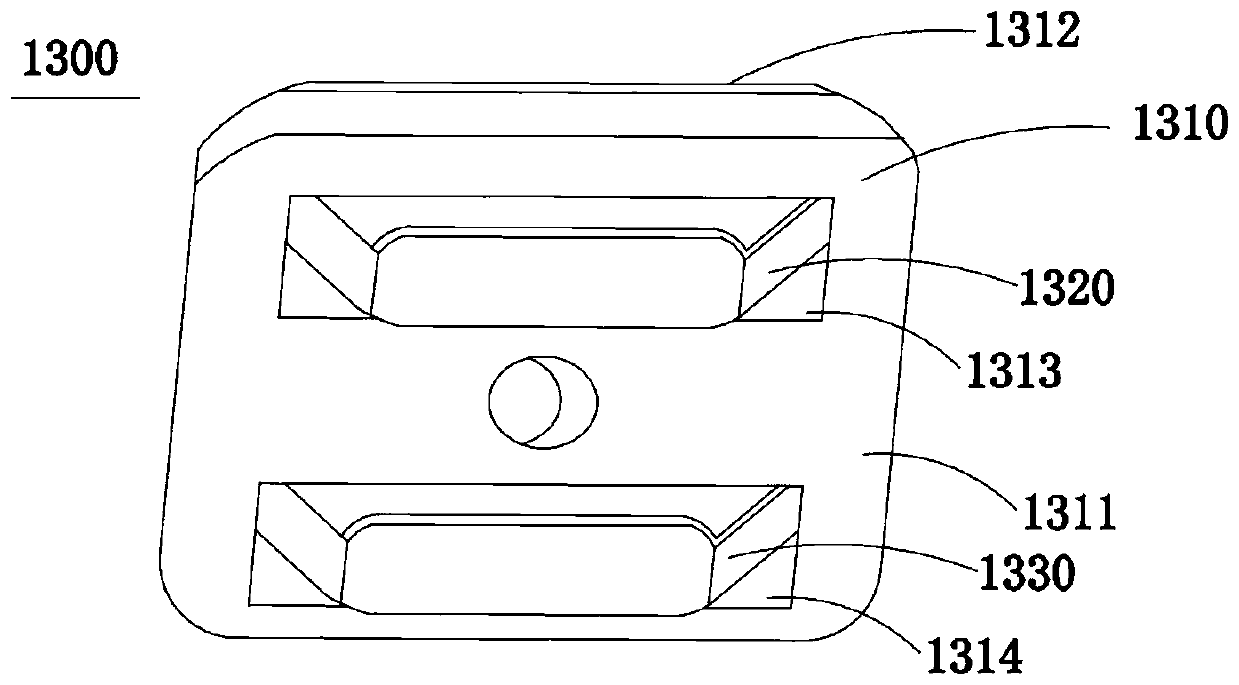
[0027] Please refer to Figure 1 to Figure 3 , figure 1 It is a partial three-dimensional schematic diagram of the lens adjustment module of the present invention, figure 2 for figure 1 A partially enlarged schematic diagram of , image 3 It is a three-dimensional schematic diagram of the first driving component.

[0028] The present invention provides a projection de...


PUM


Abstract

The invention relates to a lens adjusting module and a projection device. The lens adjusting module comprises a base, a support component, a first drive component and a first drive unit. The base is provided with a first side. The support component is provided with a third side. The third side corresponds to the first side, and the third side is provided with a first holding space. The first holding space is provided with a first surface and a second surface in the first direction. The first surface and the second surface are oppositely arranged. The first drive component comprises a first drive block and a first elastic component. The first elastic component is arranged on the first drive block and exposes out of the first drive block. The first drive component is placed in the first holding space, and the first drive component abuts against the first surface and the second surface. The first drive unit is connected with the first drive component; the first drive unit is used to drive the first drive component to bring the support rod and the lens to move in the first direction. According to the invention, while the drive component is being driven by the drive unit, the support component and the lens are subject to displacement, which eliminates the empty stroke and increases the use feel and the user's experience.

Description

technical field [0001] The invention relates to the field of projection devices, in particular to a lens adjustment module and a projection device having the lens adjustment module. Background technique [0002] In recent years, large screen has become the most popular keyword in the display field, and the product in the leading position of large screen is none other than the projection device. With the decline in the price of the projection device and the enrichment of its functions, the projection device market has obtained unprecedented development opportunities. , which are widely used in homes, offices, schools and entertainment venues. [0003] Generally, after the position of the projection device is determined, the position of the projection lens is adjusted by the driving unit, so that the projected image is located at the target position, thereby ensuring the projection effect. In the existing projection device, due to the actual manufacturing tolerance of the par...

Claims


Application Information

Patent Timeline
Patent Type & Authority Patents(China)
IPC IPC(8): G03B21/14
Inventor 萧启宏何文中
Owner QISDA OPTRONICS (SUZHOU) CO LTD
Why Eureka
Try Eureka