Connector and electronic equipment

A technology for connectors and locking parts, which is applied in the directions of connection, circuit, printed circuit, etc., can solve the problem of being difficult to use for circuit boards with various thicknesses, and achieve the effect of stable installation

Active Publication Date: 2017-08-18
JAPAN AVIATION ELECTRONICS IND LTD +1
View PDF6 Cites 0 Cited by
  • Summary
  • Abstract
  • Description
  • Claims
  • Application Information

AI Technical Summary

Problems solved by technology

That is, it is difficult to apply the frame body 920 of Patent Document 1 to circuit boards having various thicknesses.

Method used


Image

  • Connector and electronic equipment
  • Connector and electronic equipment
  • Connector and electronic equipment

Examples


Embodiment Construction

[0041] The present invention can be realized in various modifications or in various forms. Hereinafter, a specific embodiment shown in the drawings will be described in detail as an example. The drawings and embodiments do not limit the present invention to the specific form disclosed here, and all modifications, equivalents, and substitutions within the scope of the appended claims are included in the claims of the present invention.

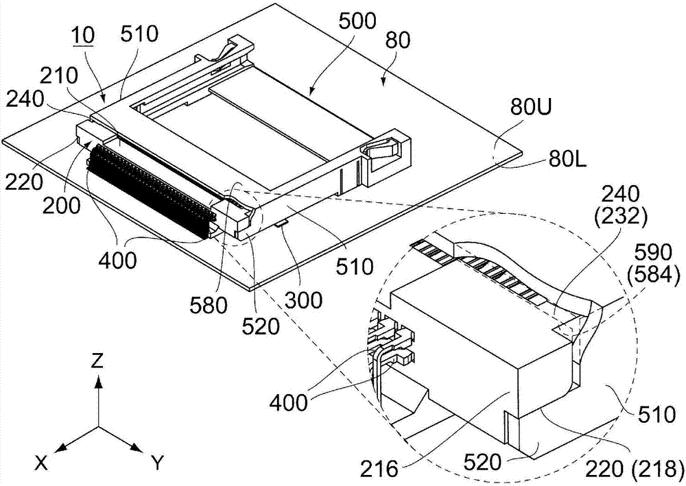
[0042] Such as figure 1 As shown, the connector 10 according to the embodiment of the present invention is a board connector mountable on an object (circuit board) 80 . In addition, the connector 10 of this embodiment is a card connector connectable to a connection object (not shown) such as a card. However, the present invention is also applicable to connectors other than card connectors.

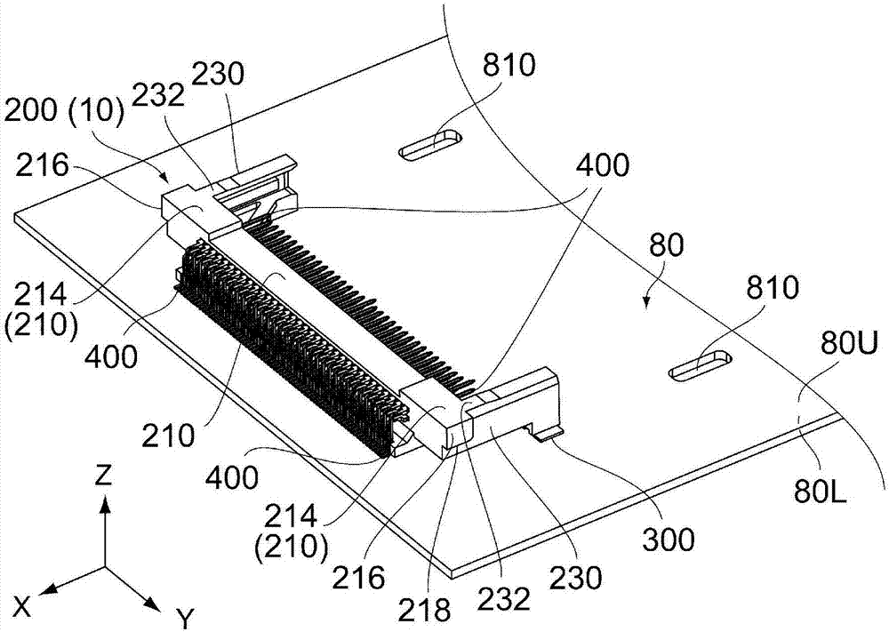
[0043] Such as figure 2 As shown, the circuit board 80 has an upper surface 80U and a lower surface 80L in the vertical direction (Z direction). The ...


PUM


Abstract

A connector (10) can be mounted to an object (80) having a lock section (820). The connector (10) is provided with a housing (200) and a frame (500). The housing (200) has a pressing section (220) and a support section (240). In a mounted state in which the connector (10) is mounted to the object (80), the housing (200) is affixed to the object (80). The frame (500) has a section (590) to be supported, a section (530) to be pressed, and a section (560) to be locked. When the connector (10) is in the mounted state, the section (590) to be supported is located between, in the front-rear direction (X), the section (530) to be pressed and the section (560) to be locked and is supported from below by the support section (240) in the vertical direction (Z) intersecting the front-rear direction (X). In the mounted state, the section (530) to be pressed is pressed from above by the pressing section (220). In the mounted state, the section (560) to be locked applies force to the lock section (820) from below.

Description

technical field [0001] The present invention relates to a connector mounted on an object such as a circuit board. The connector includes a case and a frame respectively mounted on the object. Background technique [0002] This type of connector is disclosed in Patent Document 1, for example. [0003] Such as Figure 25 As shown, the IC card connector (connector) 900 disclosed in Patent Document 1 includes a housing 910 and a housing 920 respectively mounted on a circuit board 990 . The frame body 920 has an engaging piece 922 and an upper plate portion 924 . In addition, the housing 920 holds a ground terminal 930 . The ground terminal 930 has two engaging claws 932 . Protruding ends 934 are respectively formed on the engaging claws 932 . Mounting holes 992 are formed in the circuit board 990 . When the connector 900 is mounted on the circuit board 990 , the housing 910 is first fixed to the circuit board 990 . Next, the engaging piece 922 and the upper plate portion 9...

Claims


Application Information

Patent Timeline
Patent Type & Authority Applications(China)
IPC IPC(8): H01R12/71H01R13/46
CPCH01R12/7052H01R12/714H05K2201/10189H05K3/303H05K2201/09063H01R12/7023Y02P70/50
Inventor 市川久芳和田隆光服部新哉
Owner JAPAN AVIATION ELECTRONICS IND LTD
Why Eureka
Try Eureka