Ultra-wide-band microstrip patch antenna and multi-frequency antenna array

A microstrip patch antenna and microstrip patch technology, applied in the field of antennas, can solve problems such as narrow antenna bandwidth, antenna feed dispersion, poor cross-polarization pattern, etc., and achieve the effect of solving the problem of very narrow standing wave bandwidth

Pending Publication Date: 2017-08-22
ANPULUO SUZHOU COMM TECH CO LTD
View PDF5 Cites 7 Cited by
  • Summary
  • Abstract
  • Description
  • Claims
  • Application Information

AI Technical Summary

Problems solved by technology

[0004] In view of this, the purpose of the present invention is to overcome the deficiencies in the prior art, to provide a kind of ultra-wideband microstrip patch antenna and multi-frequency antenna array, to solve the narrow antenna bandwidth in the prior art, the antenna feeding dispersion problem and the direction diagram Poor cross polarization, in multi-frequency and multi-column antennas, solves the problem of high and low frequency mutual coupling

Method used


Image

  • Ultra-wide-band microstrip patch antenna and multi-frequency antenna array
  • Ultra-wide-band microstrip patch antenna and multi-frequency antenna array
  • Ultra-wide-band microstrip patch antenna and multi-frequency antenna array

Examples


Embodiment Construction

[0038] In order to make the purpose, technical solution and advantages of the present invention clearer, the technical solution of the present invention will be described in detail below. Apparently, the described embodiments are only some of the embodiments of the present invention, but not all of them. Based on the embodiments of the present invention, all other implementations obtained by persons of ordinary skill in the art without making creative efforts fall within the protection scope of the present invention.

[0039] The technical solutions of the present invention will be described in further detail below with reference to the accompanying drawings and embodiments.

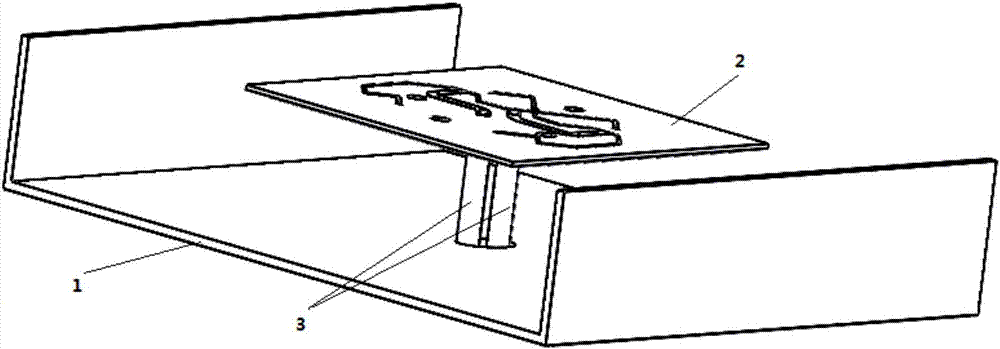
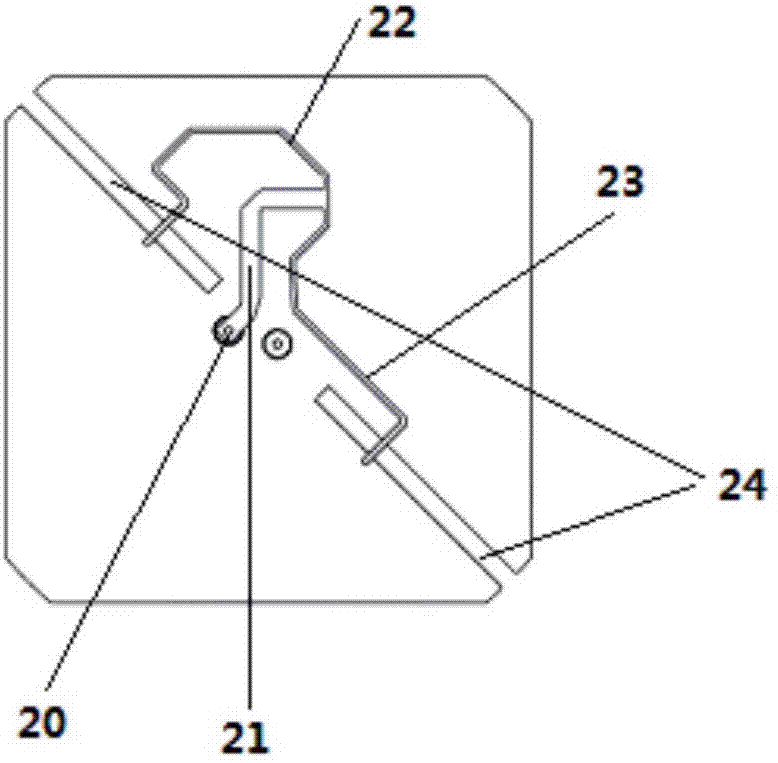
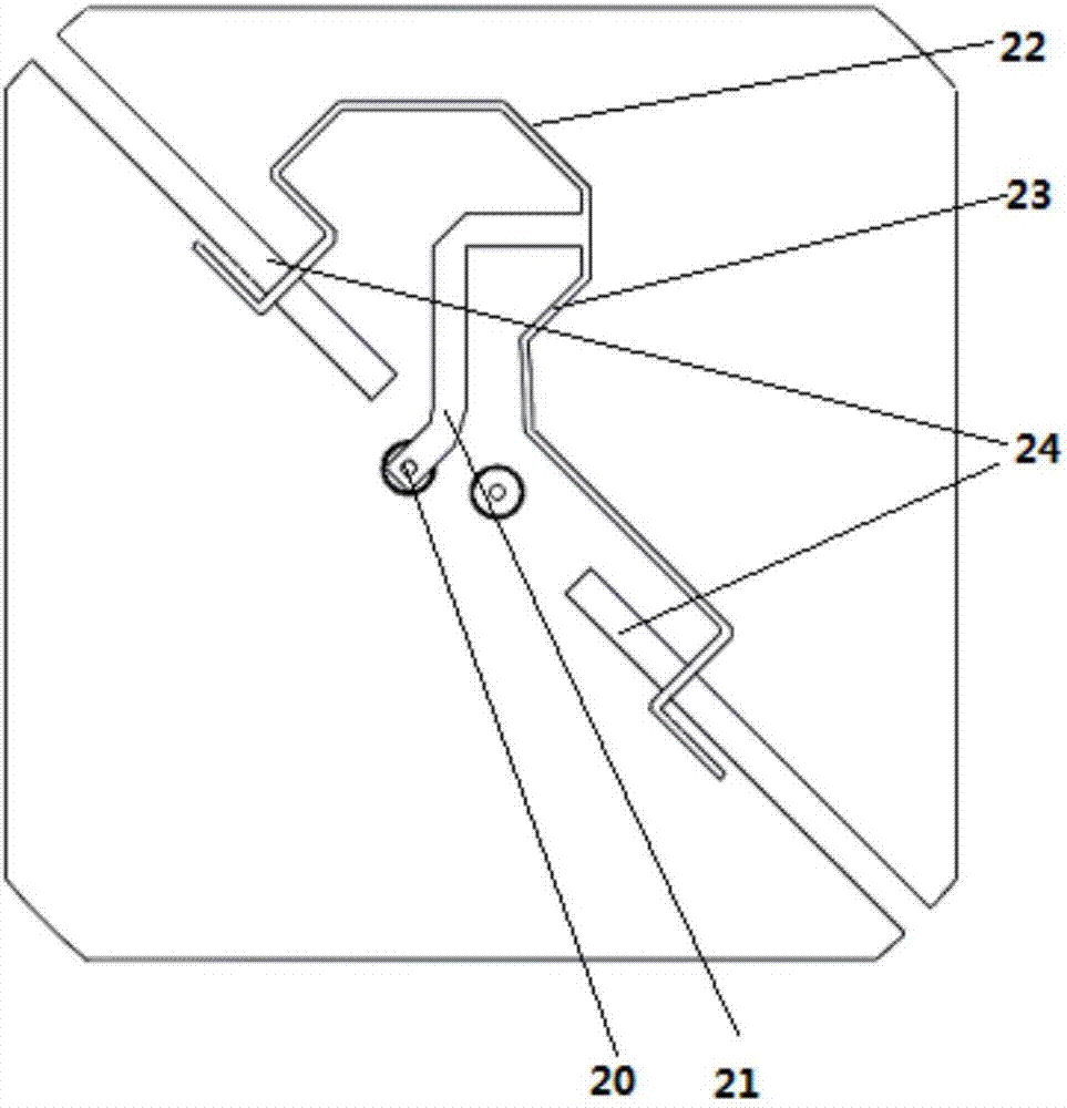
[0040] see figure 1 with figure 2 , an ultra-wideband microstrip patch antenna provided by an embodiment of the present invention, comprising a metal reflector 1 and a radiation patch device 2 arranged above the metal reflector 1; wherein,

[0041] The radiation patch device 2 includes a reflection p...


PUM


Abstract

The invention relates to an ultra-wide-band microstrip patch antenna and a multi-frequency antenna array. The microstrip patch antenna comprises a metal reflective plate and a radiation patch apparatus above the metal reflective plate; a metal patch and two gaps with opening slots in a first straight line direction are arranged on a microstrip patch layer; the opening slots of the gaps in the first straight line direction are opposite in directions; a feed network layer comprises a first feed input port, a first power division node, a first feeder line, a second feeder line and a third feeder line; one end of the first feeder line is connected with the first feed input port while the other end is connected with the input end of the first power division node; and the fixed ends of the second feeder line and the third feeder line are connected with the output end of the first power division node separately while the free ends extend towards the same side of the two gaps in the first straight line direction separately to cross over the two gaps in the first straight line direction respectively. By virtue of the technical scheme provided by the invention, the problems of antenna feed chromatic dispersion, poor directional diagram cross polarization and cross coupling of different frequencies in a multi-frequency antenna can be solved.

Description

technical field [0001] The invention relates to the technical field of antennas, in particular to an ultra-wideband microstrip patch antenna and a multi-frequency antenna array. Background technique [0002] The antenna is an energy conversion device in the mobile communication system. In mobile communications, directional antennas use half-wave symmetric dipoles to form antennas. Generally speaking, the height of half-wave symmetric dipoles is about a quarter of the wavelength, and it is difficult to reduce the height. At present, multi-frequency and multi-column antennas are the industry trend. However, the half-wave symmetric vibrator cannot solve the problem of high and low frequency mutual coupling in multi-frequency multi-column antennas. It is also a major problem that all antenna manufacturers cannot effectively solve at present. [0003] The patch antenna instead of the half-wave symmetric element can solve the above problems. For example, the disclosed name of ...

Claims


Application Information

Patent Timeline
Patent Type & Authority Applications(China)
IPC IPC(8): H01Q1/36H01Q1/38H01Q1/50H01Q13/08H01Q19/13H01Q21/00
CPCH01Q1/36H01Q1/38H01Q1/50H01Q13/085H01Q19/13H01Q21/00
Inventor 罗英涛
Owner ANPULUO SUZHOU COMM TECH CO LTD
Why Eureka
Try Eureka