Safe and adjustable plate drilling equipment

A technology for drilling equipment and plates, applied in drilling/drilling equipment, metal processing equipment, boring/drilling, etc. The effect of convenient movement and handling, prevention of safety accidents, and simple structure

Active Publication Date: 2017-08-25
CHONGQING DONGKE MOLD MFG
View PDF8 Cites 14 Cited by
  • Summary
  • Abstract
  • Description
  • Claims
  • Application Information

AI Technical Summary

Problems solved by technology

[0002] In the existing technology, the punching operation of the plate generally relies on the workers to place the workpieces on the punching machine one by one, adjust the punching position, and punch the plate. It may cause deviations in the opening positions between the plates, and the efficiency of this method is very low. In addition, the drilling bits on the existing drilling machines are exposed, which is easy to cause the drilling bits to be damaged during handling or moving. Shaking will cause equipment damage, and at the same time, it will prevent personnel misoperation from causing safety accidents. Therefore, it is necessary to propose a punching equipment with a high degree of automation and safety.

Method used


Image

  • Safe and adjustable plate drilling equipment
  • Safe and adjustable plate drilling equipment
  • Safe and adjustable plate drilling equipment

Examples


Embodiment Construction

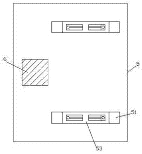
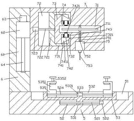
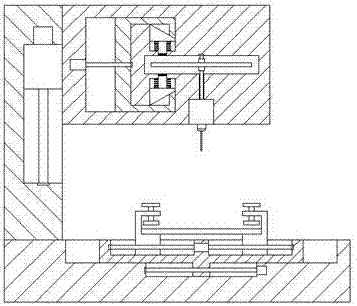
[0023] Such as Figure 1-Figure 5 As shown, a safe and adjustable plate punching equipment of the present invention includes a base 5 and a punching mechanism 7 arranged above the top of the base 5, and a column 6 is arranged on the top end surface of the left side of the base 5. A first sliding groove 51 is symmetrically arranged in the front and back of the top end surface on the left side of the base 5, and a second sliding groove 52 is arranged at the middle position of the inner bottom wall of each of the first sliding grooves 51, and a second sliding groove 52 is arranged in the second sliding groove 52. The first threaded rod 521 extending left and right, the first sliding groove 51 is slidably connected with the adjusting sliding block 53, the inside of the punching mechanism 7 is provided with a control sliding cavity 72, and the inside of the control sliding cavity 72 is on the right side. Protruding block 73 is provided, and described protruding block 73 is provided...


PUM


Abstract

The invention discloses safe and adjustable plate drilling equipment which comprises a base and a drilling mechanism arranged above the top of the base, wherein a vertical column is arranged on the end surface at the top of the left side of the base; two first sliding grooves are formed in the end surface at the top of the left side of the base in a manner of being symmetric in the front-back direction; a second sliding groove is formed in the middle of the inner bottom wall of each of the first sliding grooves; a first threaded rod arranged in a manner of extending in the left-right direction is arranged in each of the second sliding grooves; an adjusting sliding block is in sliding fit connection with the interior of each of the first sliding grooves; a manipulating sliding cavity is formed in the drilling mechanism; a convex block is arranged in the right side of the manipulating sliding cavity; a locking cavity arranged in a manner of extending towards the right side is formed in the convex block; a drilling motor is fixedly arranged in the end surface at the bottom of the drilling mechanism; a drilling bit is connected to the bottom of the drilling motor in a matched manner; a through hole is formed between the middle of the top of the drilling motor and the middle of the bottom of the locking cavity; and a rotating shaft arranged in a manner of extending in the up-down direction is in transition fit connection with the interior of the through hole. According to the safe and adjustable plate drilling equipment, the structure is simple, the safety is high, and both the drilling efficiency and the drilling precision are improved.

Description

technical field [0001] The invention relates to the technical field of punching, in particular to a safe and adjustable plate punching device. Background technique [0002] In the existing technology, the punching operation of the plate generally relies on the workers to place the workpieces on the punching machine one by one, adjust the punching position, and punch the plate. It may cause deviations in the opening positions between the plates, and the efficiency of this method is very low. In addition, the drilling bits on the existing drilling machines are exposed, which is easy to cause the drilling bits to be damaged during handling or moving. Shaking occurs, causing equipment damage, and at the same time, preventing personnel misoperation from causing safety accidents. Therefore, it is necessary to propose a punching equipment with a high degree of automation and safety. Contents of the invention [0003] The technical problem to be solved by the present invention is...

Claims


Application Information

Patent Timeline
Patent Type & Authority Applications(China)
IPC IPC(8): B23B39/00B23B47/00B23B47/20B23B47/06B23Q3/06
CPCB23B39/00B23B47/00B23Q3/06B23Q5/10B23Q5/40
Inventor 何杨波
Owner CHONGQING DONGKE MOLD MFG
Why Eureka
Try Eureka