A station switching method for a wireless shunting locomotive signal and monitoring system

A technology for shunting locomotives and monitoring systems, applied in the field of rail transit, can solve problems such as the inability to determine the position of the front end of the train, the short distance, and the inability to play the system functions in time, so as to avoid the initialization and recalculation process.

Active Publication Date: 2019-01-29
SIGNAL & COMM RES INST OF CHINA ACAD OF RAILWAY SCI +3
View PDF3 Cites 0 Cited by
  • Summary
  • Abstract
  • Description
  • Claims
  • Application Information

AI Technical Summary

Problems solved by technology

The on-board main engine generally obtains the station number and yard number information of the incoming station through the point-type answering locator installed on the ground to perform station switching. It can also be switched manually by the locomotive crew after the locomotive enters the station. The station switching method of this method is carried out when the locomotive is approaching the station or entering the station, or after entering the station. During this process, the system function cannot be played in time, so there are at least the following defects: First, when the locomotive passes the responding locator, it is far from the front. The shunting signal is relatively close, and the position of the front end of the train cannot be determined, so it is difficult for the system to fully protect the first signal
Secondly, if the locomotive is propelling, when the locomotive passes the transponder, the vehicle at the front may have passed several signals, that is, the system has no protective effect on the signals that have passed.
Thirdly, the transponder locator is a passive device installed at the entrance of the station, and the system cannot monitor the transponder locator online

Method used


Image

  • A station switching method for a wireless shunting locomotive signal and monitoring system
  • A station switching method for a wireless shunting locomotive signal and monitoring system
  • A station switching method for a wireless shunting locomotive signal and monitoring system

Examples


Embodiment Construction

[0019] The technical solutions in the embodiments of the present invention will be clearly and completely described below in conjunction with the accompanying drawings in the embodiments of the present invention. Obviously, the described embodiments are only some of the embodiments of the present invention, not all of them. Based on the embodiments of the present invention, all other embodiments obtained by persons of ordinary skill in the art without making creative efforts belong to the protection scope of the present invention.

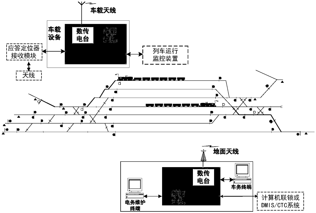
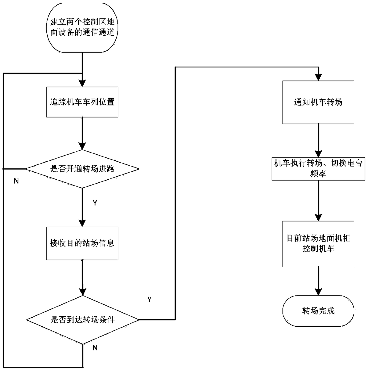
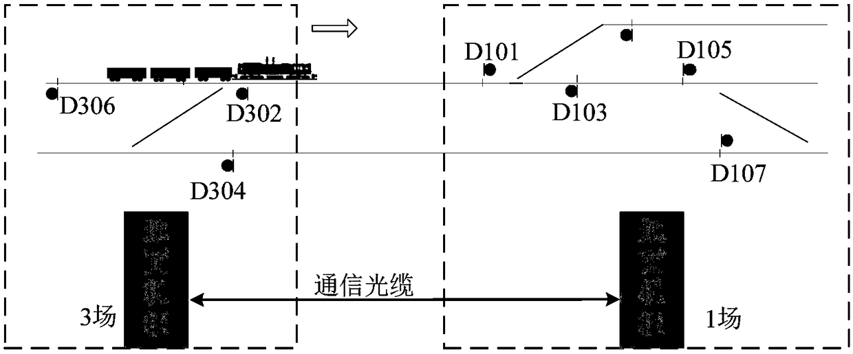
[0020] The embodiment of the present invention provides a station switching method for wireless shunting locomotive signal and monitoring system, which establishes a communication channel between the ground equipment in two adjacent control areas, and exchanges the signals and routes of the adjacent parts of the two control areas, When a registered locomotive opens a transfer approach in front of it, the ground cabinet in the control area will send ...


PUM


Abstract

The invention discloses a station-yard switching method of a shunting train protection (STP) system. The method comprises: establishing a communication channel between ground equipment of every two adjacent control zones, exchanging the adjoined part signal condition and the approach road condition of the two control zones, the ground cabinet of the control zone where a registered locomotive is located transmitting the signal condition of the adjoined areas of the two control zones to the locomotive when a transfer approach road is opened in front of the registered locomotive and informing the locomotive of performing station-yard switching in real time, switching to the control zone which the locomotive is about to enter, meanwhile, transmitting train set information of the locomotive to the corresponding ground cabinet through the communication channel, and the corresponding ground equipment directly taking over the control of the locomotive, without carrying out the process of registration, network access, and re-initialization of the train set information of the locomotive. The purpose of continuous control over the transfer operation of the locomotive is realized. The station-yard switching method of the STP system is of great significance in improving the control performance of STP systems.

Description

technical field [0001] The invention relates to the technical field of rail transit, in particular to a station switching method of a wireless shunting locomotive signal and monitoring system. Background technique [0002] The wireless shunting locomotive signal and monitoring system (STP) is a computer integrated control system used for displaying shunting locomotive signals and monitoring shunting operations at railway stations. Track the shunting locomotives operating in the station, and transmit the station yard information, shunting signals in front of the locomotives, and work orders to the on-board host through wireless channels, so as to realize shunting signals and The real-time display of roads and work sheets on the color monitor of the locomotive, combined with the train operation monitoring device, realizes the safety protection control and operation data recording of shunting operations. [0003] The system consists of two parts: ground equipment and on-board ...

Claims


Application Information

Patent Timeline
Patent Type & Authority Patents(China)
IPC IPC(8): B61L27/00B61L23/00
CPCB61L23/00B61L27/00
Inventor 冯军杨华昌闫石程君栾德杰唐汇东任宛星赵阳韩波李继东张弘志尹德胜李铁王浩然陈尚彬林炳跃尚麟宇王迪菲曹子昱刘靖远郭虹利常浩曹天睿赵小军黄天天马金鑫王新勇刘明源张少磊李燕张为盛玉张永罗妮娜牟杰黄海涛王凌峰文超周申江辉苑江涛
Owner SIGNAL & COMM RES INST OF CHINA ACAD OF RAILWAY SCI
Why Eureka
Try Eureka