
Groove wall device and method for making grooves in the ground

A land and trench technology, applied in the direction of excavation, sheet pile wall, earth mover/excavator, etc., can solve the problem that the carrier tool is not suitable

Active Publication Date: 2017-08-25
BAUER MASCH GMBH
View PDF6 Cites 5 Cited by
  • Summary
  • Abstract
  • Description
  • Claims
  • Application Information

AI Technical Summary

Problems solved by technology

For this reason, carrier tools with larger poles are not suitable

Method used


Image

  • Groove wall device and method for making grooves in the ground
  • Groove wall device and method for making grooves in the ground
  • Groove wall device and method for making grooves in the ground

Examples


Embodiment Construction

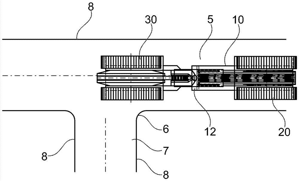
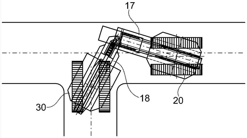
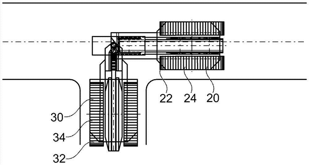
[0030] according to figure 1 with 2The partition wall arrangement 10 has a first carrier tool 20 and a second carrier tool 30 , each of which has a tracked running gear as the lower frame 22 , 32 . A first upper carrier 24 with a frame-like first superstructure 26 is arranged on the first lower carrier 22 via a swivel bearing 23 . Correspondingly, the second upper bracket 34 is rotatably supported on the second lower bracket 32 ​​of the second carrier transport tool 30 via the rotation bearing 33 . A second upper structure 36 similar to a frame structure is fixed on the second upper bracket 34 .

[0031] The first carrier transport means 20 and the second carrier transport means 30 are connected to each other via beam-shaped cross members 12 . To this end, in the upper region of the first superstructure 26 of the first carrier transport 20 is mounted a horizontally protruding first cross member 17 which is coupled via a pivot joint 19 with a vertically directed pivot axis t...


PUM


Abstract

The invention relates to a groove wall device and a method for making grooves in the ground for generating a groove in the ground to isolate or partition the wall. The groove wall device has a carrier device on which a floor removal unit is vertically adjustably mounted. The invention is characterized in that a first carrier device and a second carrier device are provided, which are connected to one another by way of a yoke, and that the floor removal unit is arranged so as to be adjustable below the yoke.

Description

technical field [0001] The invention relates to a partition wall device for creating a trench in the ground for a partition wall or a cut-off wall according to the preamble of claim 1, with a carrier implement, a soil removal unit with Supported on the carrier tool in a vertically adjustable manner. [0002] The invention furthermore relates to a method for producing a trench in the ground with a partition wall arrangement according to the preamble of claim 11 , wherein the ground removal unit is lowered into the ground and in doing so the ground material was removed. Background technique [0003] Partition wall arrangements for creating trenches in the ground have long been known. As a ground removal unit, it has a so-called diaphragm wall cutter or a so-called diaphragm wall grabber. Typically, the land removal unit is arranged in a vertically adjustable manner on a column or extension arm. The mast or extension arm on the carrier tool typically has a height of 15 to 3...

Claims


Application Information

Patent Timeline
IPC IPC(8): E02F3/20E02F3/22E02F3/26E02F5/08E02D5/18
CPCE02D5/187E02F3/205E02F3/22E02F3/26E02F5/08E02D17/13E02D17/12E02D19/22E02F5/109E02F5/12E02F5/223E02F5/30
Inventor C.赫尔曼L.A.胡贝尔L.魏克斯勒
Owner BAUER MASCH GMBH
Learn More