
Concrete pouring device for arch wall lining trolley in single track railway tunnel and mounting method of concrete pouring device

A technology for lining trolleys and single-track railways is applied in the field of concrete pouring devices for lining trolleys for arch walls, and can solve the problems of uneven force on the trolleys, local displacement of the formwork system, and large interference.

Inactive Publication Date: 2017-08-25
ERCHU CO LTD OF CHINA RAILWAY TUNNEL GRP
View PDF7 Cites 0 Cited by
  • Summary
  • Abstract
  • Description
  • Claims
  • Application Information

AI Technical Summary

Problems solved by technology

[0002] The arch wall lining trolley is a hydraulic system used for the secondary lining of the tunnel arch wall. The arch wall lining trolley also includes a formwork system that cooperates with the inner wall of the tunnel. The formwork system reserves a concrete pouring window during the processing of the factory. , the traditional concrete pouring usually adopts the "single pipe by window" method, that is, after the concrete delivery pump and supporting pipelines are connected, the concrete is carried out according to the principle of "bottom to top, one side pouring", resulting in the concrete being poured at a single window It is prone to "hump", "cold peak" and the phenomenon of uneven force on the trolley when the amount of concrete poured on one side is too large, which leads to local displacement of the formwork system, which in turn leads to the occurrence of concrete quality problems
[0003] For example, the Chinese utility model patent application with the application number 201120297566.7 discloses a secondary lining trolley for tunnel side walls and arch walls formed at one time, which solves the problem of secondary lining concrete construction of existing tunnels. Separate construction has the problems of large interference, time-consuming and labor-intensive, and poor effect

Method used


Image

  • Concrete pouring device for arch wall lining trolley in single track railway tunnel and mounting method of concrete pouring device
  • Concrete pouring device for arch wall lining trolley in single track railway tunnel and mounting method of concrete pouring device
  • Concrete pouring device for arch wall lining trolley in single track railway tunnel and mounting method of concrete pouring device

Examples


Embodiment Construction

[0032] The specific embodiments of the present invention will be further described in detail below.

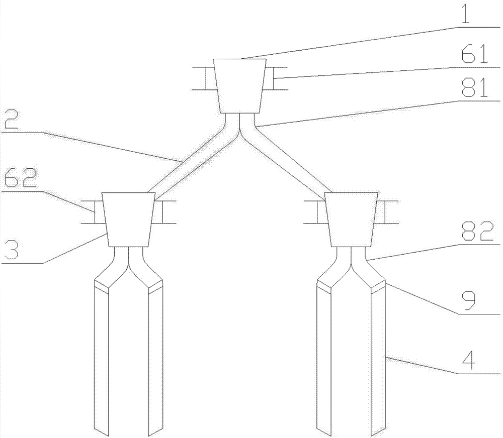
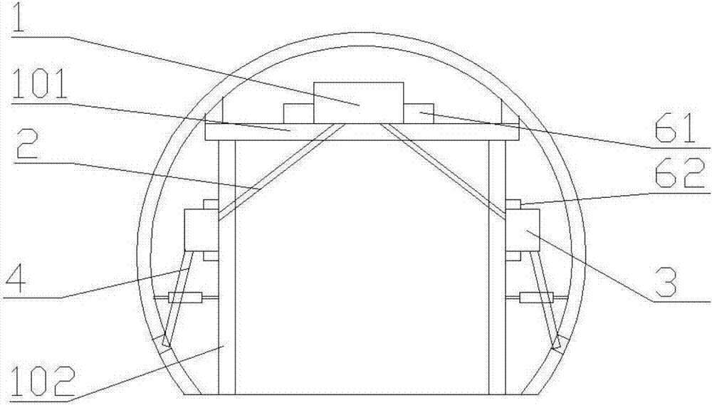
[0033] as attached Figure 1-2 As shown, a concrete pouring device for an arch wall lining trolley in a single-track railway tunnel includes: a first hopper 1, a first support device 61, a first steel pipe elbow 81, a first shuttle groove 2, a second hopper 3, The second support device 62, the second steel pipe elbow 82, the connecting hose 9 and the first chute 4, the first hopper 1 is fixed on the top beam 101 of the arch wall lining trolley through the first support device 61 , the lower part of the first hopper 1 is connected with two first steel pipe elbows 81, the two first steel pipe elbows 81 are symmetrically arranged, and the first steel pipe elbows 81 are connected to the first shuttle slot 2, the first shuttle slot 2 communicates with the second hopper 3, and the second hopper 3 is fixedly arranged on the longitudinal beams 102 on both sides of the arch wall linin...


PUM


Abstract

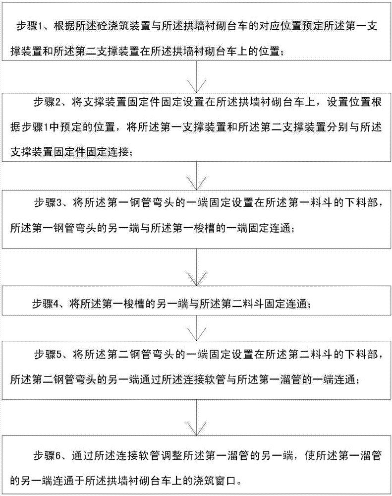
The invention discloses a concrete pouring device for an arch wall lining trolley in a single track railway tunnel and a mounting method of the concrete pouring device. The device comprises a first hopper, a first support device, first steel elbows, a first shuttle chute, a second hopper, a second support device, second steel elbows, a connecting hose and a first chute, wherein the first hopper is fixed on the arch wall lining trolley through the first support device; a discharge part of the first hopper is communicated with the two first steel elbows which are communicated with the first shuttle chute; the first shuttle chute is communicated with the second hopper which is fixed on the arch wall lining trolley through the second support device; a discharge part of the second hopper is communicated with the two second steel elbows which are connected with the first chute through the connecting hose. With adoption of the concrete pouring device, phenomena of hump, cold front and displacement of a formwork system are effectively eliminated.

Description

technical field [0001] The invention belongs to the technical field of tunnel engineering construction, and in particular relates to a concrete pouring device and an installation method for an arch wall lining trolley in a single-track railway tunnel. Background technique [0002] The arch wall lining trolley is a hydraulic system used for the secondary lining of the tunnel arch wall. The arch wall lining trolley also includes a formwork system that cooperates with the inner wall of the tunnel. The formwork system reserves a window for concrete pouring during the processing of the factory. , Traditional concrete pouring usually adopts the method of "single pipe by window", that is, after the connection of the concrete delivery pump and supporting pipelines is completed, the concrete is carried out according to the principle of "bottom-up, one-sided pouring", resulting in concrete being poured at a single window. It is easy to appear "hump", "cold peak" and the phenomenon of ...

Claims


Application Information

Patent Timeline
Patent Type & Authority Applications(China)
IPC IPC(8): E21D11/10
CPCE21D11/10E21D11/105
Inventor 尚军单华亮赵伟周勇军马占群牛瑞梁振
Owner ERCHU CO LTD OF CHINA RAILWAY TUNNEL GRP
Learn More