Combined heat supply device using heat storage electric boiler and air source heat pump and heat supply method thereof

A regenerative electric boiler and air source heat pump technology, which is applied in household heating, space heating and ventilation, space heating and ventilation details, etc. Effect

Active Publication Date: 2017-08-25
北京马六点科技有限公司
View PDF4 Cites 9 Cited by
  • Summary
  • Abstract
  • Description
  • Claims
  • Application Information

AI Technical Summary

Problems solved by technology

[0007] The first purpose of the present invention is to solve the technical problem of low energy efficiency in the prior art that neither the regenerative electric boiler nor the air source heat pump is suitable for supplying heat for a wide range of temperature changes from below zero to above zero in the north alone , provide a central controller to control the two to provide hot air and hot water, use air source heat pump when the temperature is high, and use thermal storage electric boiler when the temperature is low, the central controller is equipped with environmental and indoor temperature measuring devices, and monitors The temperature of the water tank is used as the basis for judging the combined heat supply device of the regenerative electric boiler and the air source heat pump

Method used


Image

  • Combined heat supply device using heat storage electric boiler and air source heat pump and heat supply method thereof
  • Combined heat supply device using heat storage electric boiler and air source heat pump and heat supply method thereof
  • Combined heat supply device using heat storage electric boiler and air source heat pump and heat supply method thereof

Examples


Embodiment 1

[0027] refer to figure 1 As shown, the present invention provides a heat supply method of the present invention according to the above-mentioned thermal storage electric boiler and air source heat pump combined heat supply device.

[0028] In order to realize the first purpose of the present invention, the technical scheme adopted in the present invention is as follows:

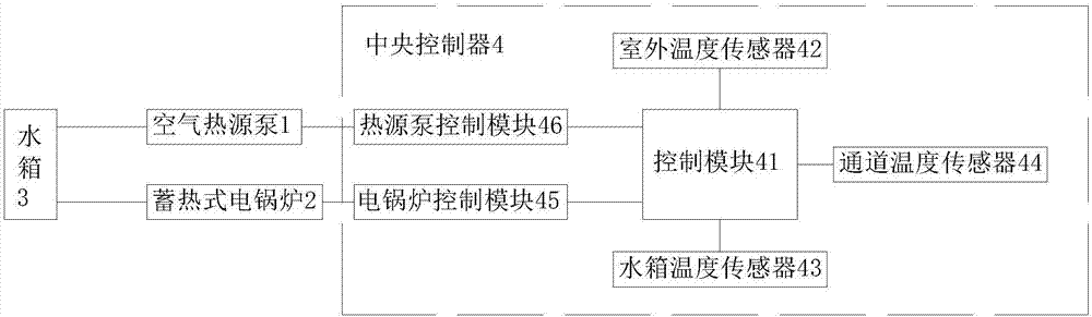
[0029] A thermal storage electric boiler and air source heat pump combined heating device of the present invention comprises the following components: an air source heat pump 1, a thermal storage electric boiler 2, a water tank 3, and a central controller 4 .

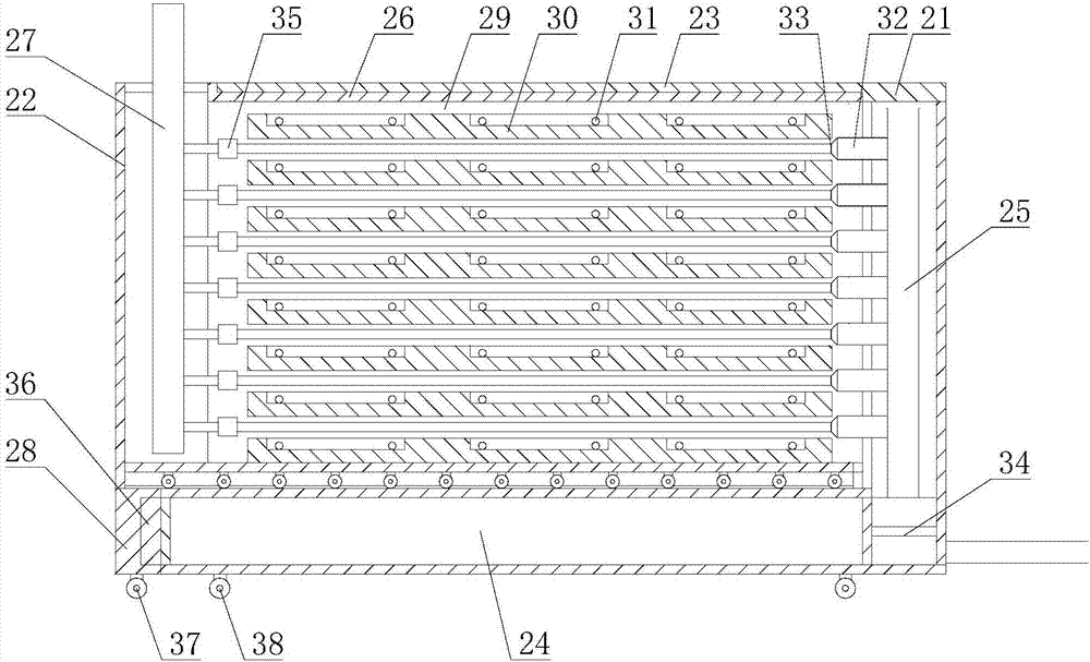
[0030] The regenerative electric boiler 2 and the air source heat pump 1 are all connected to the central controller 4 for data; further, the regenerative electric boiler 2 includes an outer box 21 and an inner box 21, and the outer box The upper part of the body 21 is provided with an electric boiler outer storage box 23 with an opening on one side,...

Embodiment 2

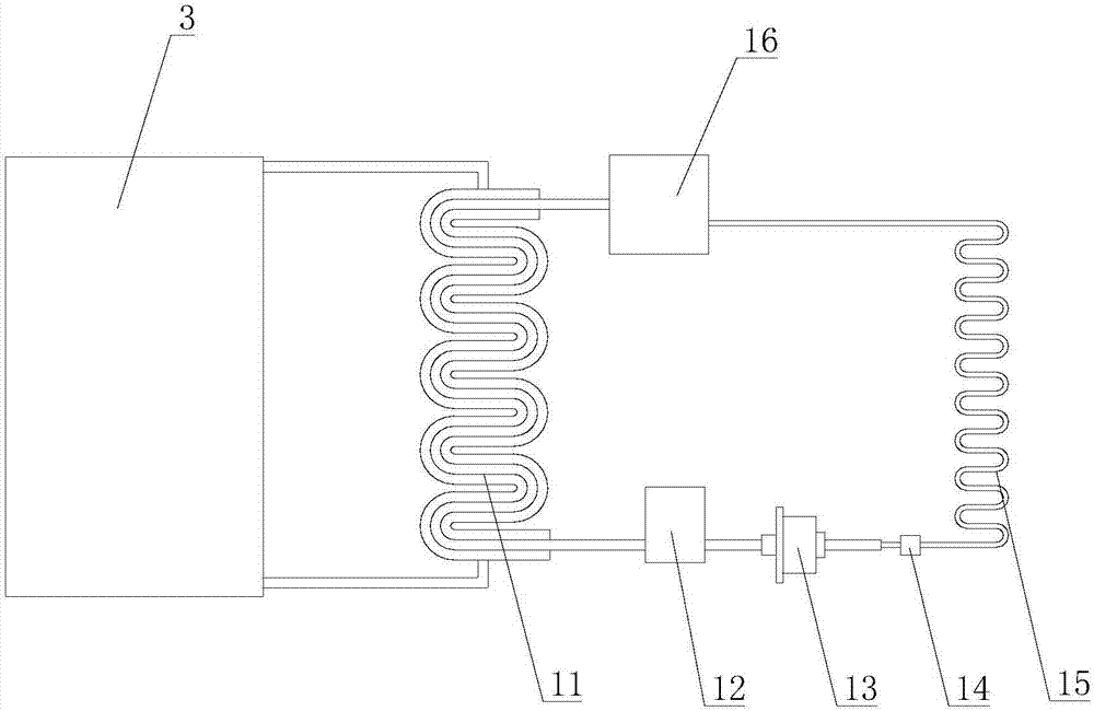
[0034] The air source heat pump 1 is used to heat the water in the water tank by using the air source heat pump; the heat storage electric boiler 2 is used to use the low-valley electric energy to store heat, and then use the accumulated heat to heat the water in the water tank; the water tank 3 is used to store heat water, and keep the hot water warm; the central controller 4 is used to detect the outdoor temperature of the air source heat pump, judge and control the air source heat pump to provide heat for the water tank or the regenerative electric boiler to provide heat for the water tank.

[0035] The water tank 3 communicates with the heat storage electric boiler 2 and the air source heat pump 1 respectively, and the heat storage electric boiler 2 and the air source heat pump 1 are also electrically connected with the central controller 4 . Detect the outdoor temperature of the air source heat pump 1 through the central controller 4, judge and control the air source heat ...

Embodiment 3

[0042]S1, preset outdoor first temperature T1 and second temperature T2, heating target temperature T0, the first temperature T1 is lower than the second temperature T2, the first temperature T1 is between -15°C and -5°C, and the second temperature T2 Between 5°C and 15°C, T0 between 20°C and 25°C; S2, the central controller detects the outdoor temperature T of the air source heat pump through the outdoor temperature sensor; S3, compares the outdoor temperature T with the first temperature T1 Compared with the second temperature T2, when the outdoor temperature T is less than or equal to the first temperature T1, perform step S4; when the outdoor temperature T is greater than the first temperature T1 and less than the second temperature T2, perform step S5; when the outdoor temperature T is greater than or equal to the second temperature T2, go to step S6; S4, the central controller controls the control module to turn off the air source heat pump, and controls the heat storage ...


PUM


Abstract

The invention discloses a combined heat supply device using a heat storage electric boiler and an air source heat pump and a heat supply method thereof. The combined heat supply device comprises the air source heat pump, the heat storage electric boiler, a water tank and a central control unit. The water tank communicates with the heat storage electric boiler and the air source heat pump. The heat storage electric boiler and the air source heat pump are further electrically connected with the central control unit. According to the combined heat supply device using the heat storage electric boiler and the air source heat pump and the heat supply method thereof, the central control unit is used for detecting the outdoor temperature of the air source heat pump and further judging and controlling whether the air source heat pump supplies heat to the water tank or the electric boiler supplies heat to the water tank, the air source heat pump is adopted when the outdoor temperature is high, and the heat storage electric boiler is adopted when the temperature is low; and the central control unit is provided with an environment and indoor temperature measuring device, the temperature of the water tank can be monitored to be used as judgment data, the defects are overcome by means of system combination, and therefore the overall heat supply is made more economical and reasonable, and the water outlet temperature can be guaranteed.

Description

technical field [0001] The invention relates to the technical field of indoor hot water supply, in particular to a combined heat supply device and heat supply method of a regenerative electric boiler and an air source heat pump. Background technique [0002] Electric boilers are mainly used for winter heating in family residences and commercial offices. However, heating in winter is one of the important factors to improve the quality of life and office efficiency. The heating methods mainly include steam heat, water heat and electric heat. However, electric heating has flexible adjustment, safety and environmental protection, and is easy to use, occupying a large heating market. [0003] At present, with the development of the economy and the improvement of the quality of life, people's demand for electricity is increasing, and the contradiction of urban electricity supply is becoming more and more prominent. Big. In order to solve this contradiction, the state has implem...

Claims


Application Information

Patent Timeline
Patent Type & Authority Applications(China)
IPC IPC(8): F24D17/02F24D17/00F24D19/10
CPCF24D17/0031F24D17/02F24D19/1054F24D2200/08F24D2200/123
Inventor 马强孙月芳马昊卓凡马羽卓凡
Owner 北京马六点科技有限公司
Why Eureka
Try Eureka