
Constant temperature water tank for calorimeter calibrating device

A technology of a verification device and a constant temperature water tank, which is applied to the measurement device, heat measurement, calorimeter, etc., can solve the problems of disturbing the water flow movement of the box, the water temperature of the water outlet of the box is not constant, and the detection of the heat meter is not accurate.

Active Publication Date: 2013-11-27
泉州七洋机电有限公司
View PDF6 Cites 4 Cited by
  • Summary
  • Abstract
  • Description
  • Claims
  • Application Information

AI Technical Summary

Problems solved by technology

[0006] The purpose of the present invention is to provide a constant temperature water tank for a heat meter verification device to solve the problem that in the prior art, when the return water flow rate of the back water after the heat meter verification is large, the water flow movement in the box will be disturbed, and the water outlet of the water outlet of the box body will be disturbed. The temperature is not constant, which makes the detection of the heat meter inaccurate

Method used


Image

  • Constant temperature water tank for calorimeter calibrating device
  • Constant temperature water tank for calorimeter calibrating device
  • Constant temperature water tank for calorimeter calibrating device

Examples


Embodiment Construction

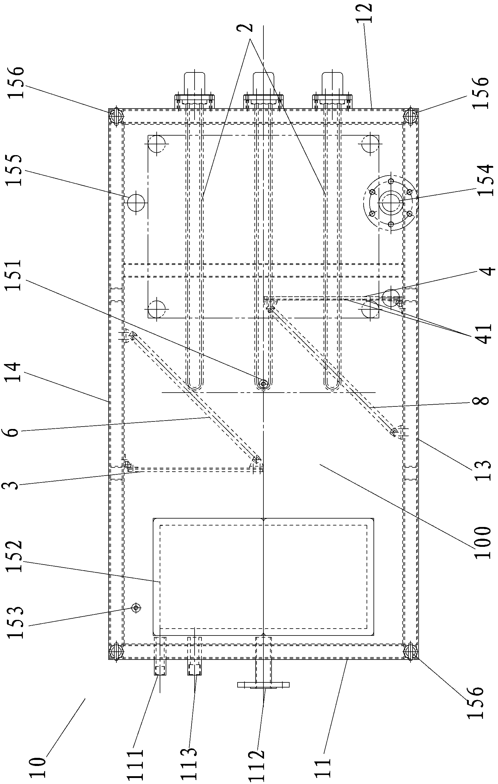
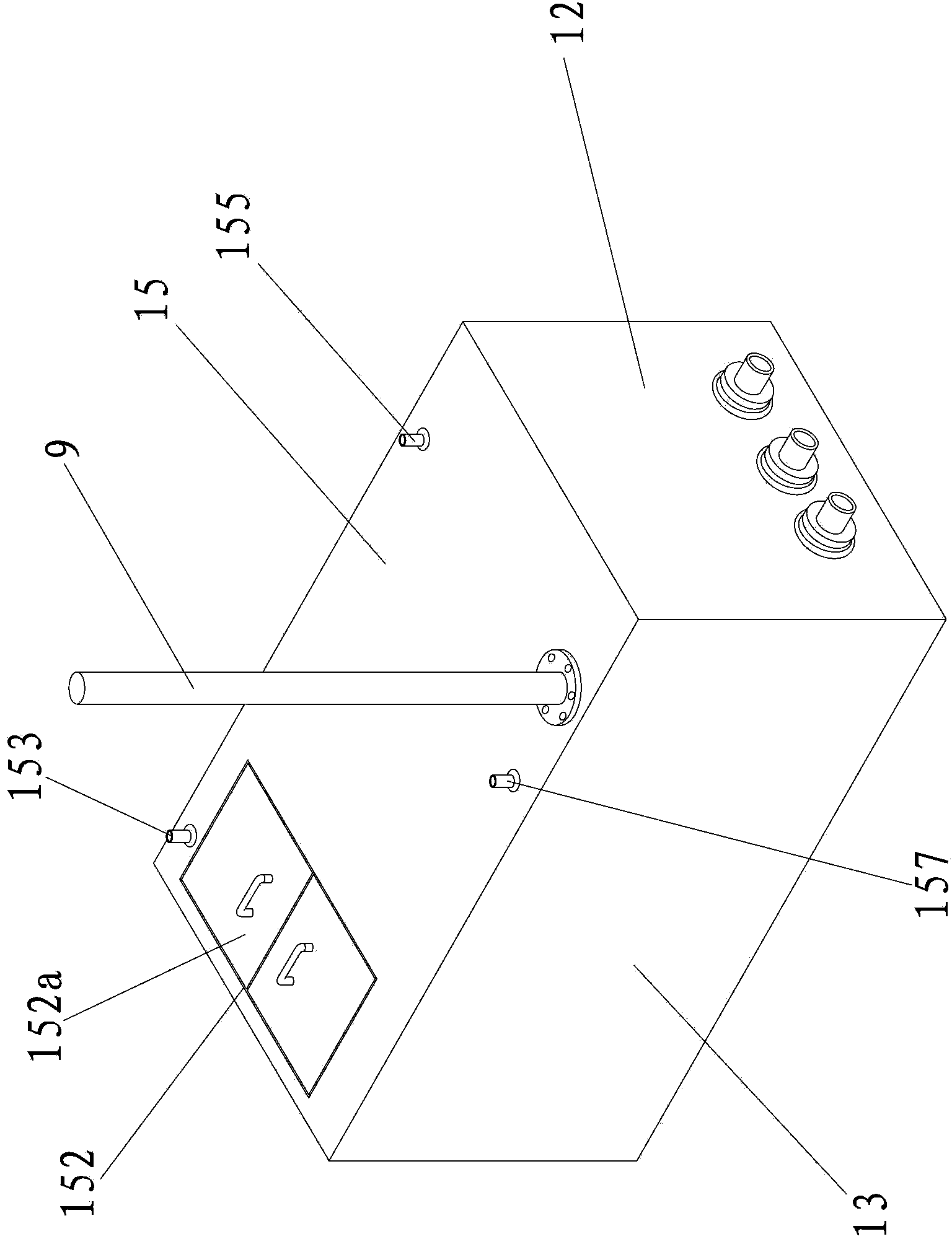
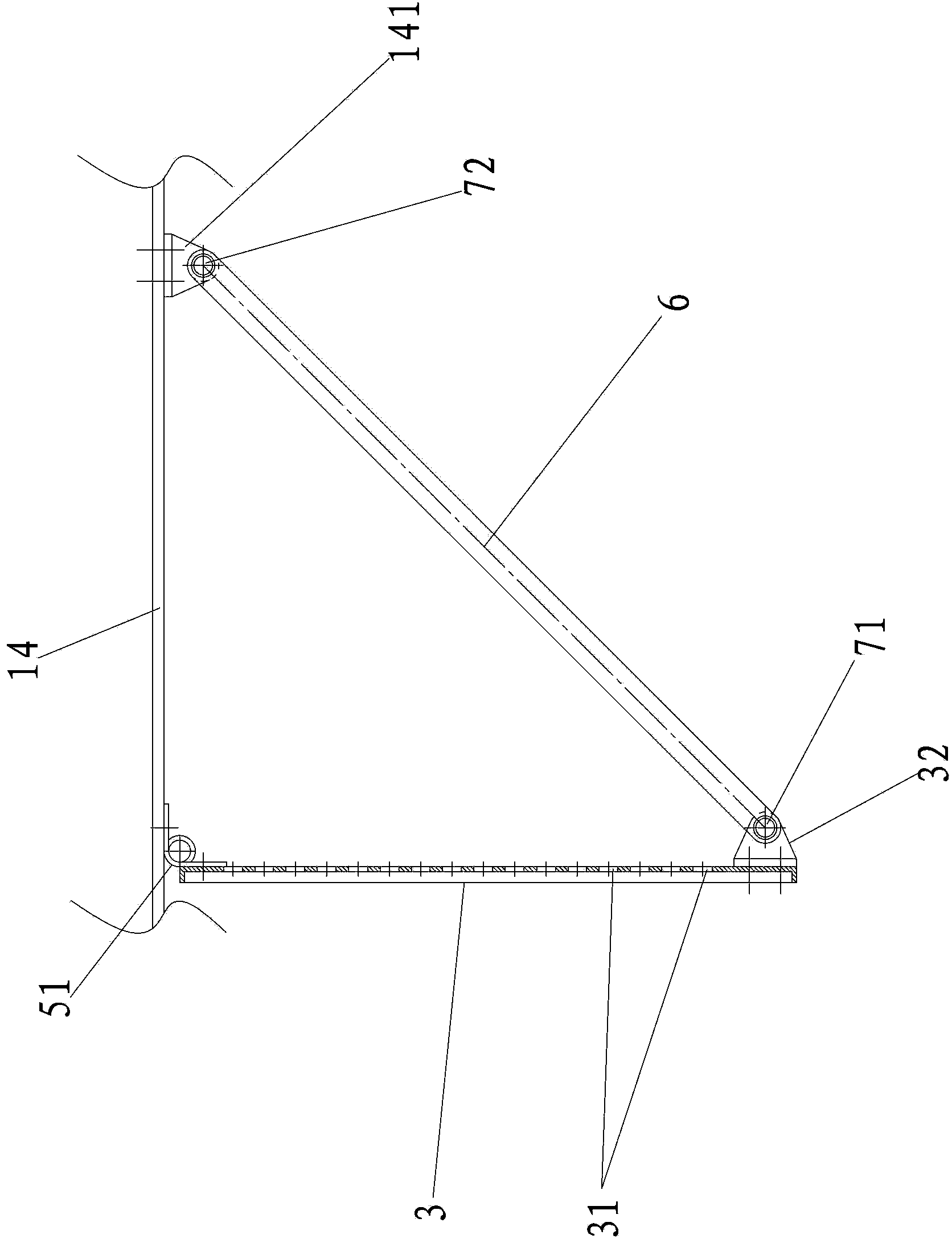
[0022] A constant temperature water tank for a calorimeter verification device of the present invention, such as Figure 1-4 Shown, comprise box body 10, and this box body 10 is surrounded by left side plate 11, right side plate 12, front side plate 13, rear side plate 14, upper top plate 15 and lower base plate (not shown in the figure). Hollow and airtight box body, the upper part of the left side plate 11 is provided with a cold water inlet 111 for external water to be injected into the box body, and the lower part of the left side plate 11 is opened with a hot water outlet 112 for hot water to flow out of the box body and for sewage drainage in the box body. Empty drain port 113, the box body 1 is provided with an electric heating element 2 at the right side of the box body 1, and the upper top plate 15 is provided with a temperature sensor installation port 151, an inspection inlet 152, and a water return port of the stabilized air getter tank 153. The water return port 1...


PUM


Abstract

The invention discloses a constant temperature water tank for a calorimeter calibrating device. The constant temperature water tank for the calorimeter calibrating device comprises a tank body and further comprises a first water blocking partition plate and a second water blocking partition plate, wherein a plurality of flushing openings are formed in the first water blocking partition plate and the second water blocking partition plate respectively in a dense distribution mode, the first water blocking partition plate is erected on the left side of a hollow chamber of the tank body, the second water blocking partition plate is erected on an electric heating element, the first water blocking partition plate and the second water blocking partition plate are oppositely arranged and mutually staggered, and a winding liquid advancing route is formed by the first water blocking partition plate and the second water blocking partition plate in the tank body. The constant temperature water tank for the calorimeter calibrating device has the advantages that the first water blocking partition plate and the second water blocking partition plate are used for blocking backwater which flows into the tank body so that the backwater can flow to a hot water outlet along the winding liquid advancing route instead of directly flowing to the hot water outlet, as a result, the situation that the backwater directly flows to the hot water outlet without being heated by the electric heating element after a calorimeter is calibrated is effectively prevented, the outlet water temperature at the hot water outlet is ensured, and the detection of the calorimeter can be accurate.

Description

technical field [0001] The invention relates to an accessory of a heat meter verification device, in particular to a constant temperature water tank of the heat meter verification device. Background technique [0002] The heat meter verification device can perform flow sensor, paired temperature sensor, calculator component verification and heat meter total verification for various heat meters; its working principle is: heating the constant temperature water tank to make the water temperature in it reach the set temperature value, start the frequency conversion water pump to send hot water into the test pipeline, flow through the standard flow meter and the heat meter to be tested, and return to the constant temperature water tank; at this time, adjust the flow rate to the set value by adjusting the flow regulating valve and the speed of the frequency conversion water pump At the flow point, put the standard thermometer and the temperature sensor of the tested meter in two c...

Claims


Application Information

Patent Timeline
IPC IPC(8): G01K19/00F24H1/20
Inventor 刘明生蒋韵坚陈沛
Owner 泉州七洋机电有限公司
Learn More