Efficient water-saving shower device

A shower device, high-efficiency technology, applied in water supply devices, indoor sanitary piping devices, water resources protection, etc., can solve problems such as waste

Active Publication Date: 2019-03-15
李润凡
View PDF6 Cites 4 Cited by
  • Summary
  • Abstract
  • Description
  • Claims
  • Application Information

AI Technical Summary

Problems solved by technology

[0003] The purpose of the present invention is to solve the problem in the prior art that the cold water pre-stored between the water he...

Method used


Image

  • Efficient water-saving shower device
  • Efficient water-saving shower device
  • Efficient water-saving shower device

Examples


Embodiment 1

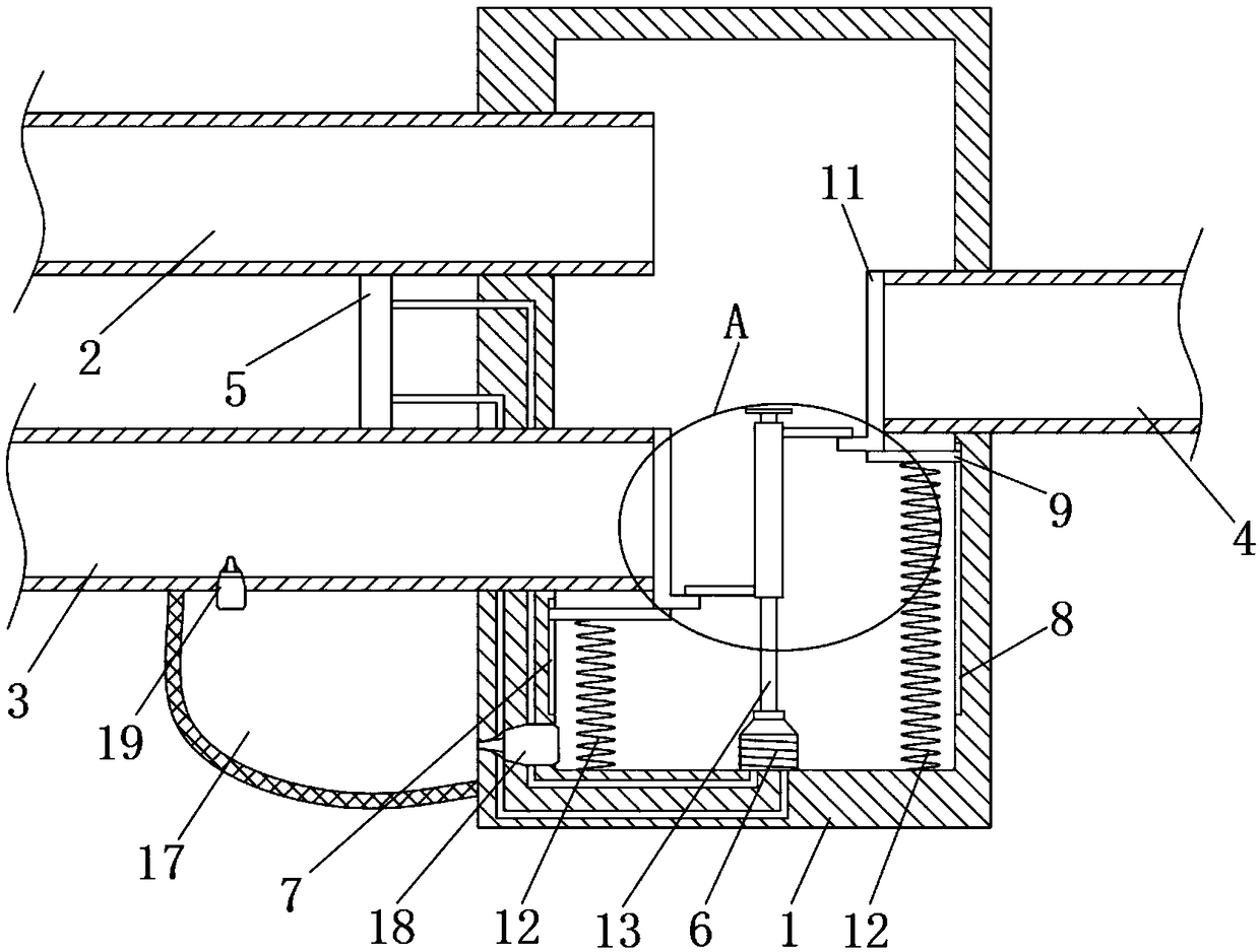
[0020] refer to Figure 1-2 , a high-efficiency water-saving shower device, including a housing 1, a hot water pipe 2, a cold water pipe 3, and a water outlet pipe 4, the hot water pipe 2 is connected to the water outlet of an external water heater, and the cold water pipe 3 is connected to an external cold water supply pipe , the water outlet pipe 4 is directly connected with the external shower head;

[0021] The housing 1 has a square structure, and a square cavity is arranged inside the housing 1. The hot water pipe 2, the cold water pipe 3, and the outlet pipe 4 are all connected to the cavity. The outlet pipe 4 is located on the other side of the casing 1. When showering, the hot water pipe 2 and the cold water pipe 3 flow out hot water and cold water respectively, and after being mixed into warm water in the casing 1, it flows out from the outlet pipe 4 for showering with people. use;

[0022] The outer walls of the hot water pipe 2 and the cold water pipe 3 are joint...

Embodiment 2

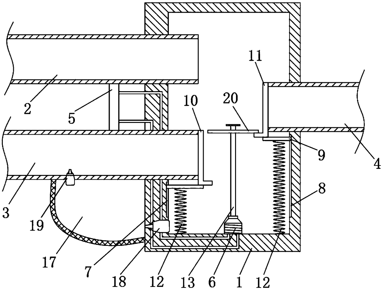
[0031] refer to image 3 The difference between this embodiment and Embodiment 1 is that the sliding device is different. The sliding device of this embodiment includes a magnetic flat plate 20, which is sleeved on the sliding post 13. During the sliding process of the magnetic flat plate 20 on the sliding post 13, first Drive the second baffle plate 11 to move so that it does not oppose the nozzle of the water outlet pipe 4. When the second baffle plate 11 does not produce a blocking effect on the nozzle of the water outlet pipe 4 at all, the magnetic plate 20 continues to move and drives the first baffle plate 10 to move. The cold water in the cold water pipe 3 enters the inside of the housing 1 .

[0032] At the beginning of the shower, the temperature of the hot water in the water heater is often low. At this time, the temperature difference between the two ends of the thermoelectric power generation piece 5 is low, and the generated current is small. The angle of the magn...


PUM


Abstract

The invention discloses an efficient water-saving shower device. The efficient water-saving shower device comprises a shell, a hot water pipe, a cold water pipe and a water outlet pipe, wherein the shell is of a square structure; a square cavity is formed in the interior of the shell; the hot water pipe, the cold water pipe and the water outlet pipe communicate with the cavity respectively; the hot water pipe and the cold water pipe are positioned on one side of the shell; the water outlet pipe is positioned on the other side of the shell; a thermoelectric power generation piece is arranged onthe outer wall of the hot water pipe and the outer wall of the cold water pipe together; and two electrodes of the thermoelectric power generation piece are connected with electromagnets through wires. When the temperature of water flowing from the hot water pipe is relatively low, two baffle plates abut against pipe openings of the water outlet pipe and the cold water pipe simultaneously, so that water inside the shell cannot flow out, water flowing from the hot water pipe can flow into an elastic water bag for storage, cold water flowing at the beginning of shower is avoided from flowing out directly to cause waste, and when the temperature of water inside the hot water pipe is increased, hot water inside the hot water pipe and cold water inside the cold water pipe are mixed inside theshell and flow out from the water outlet pipe for being used in a shower.

Description

technical field [0001] The invention relates to the technical field of shower equipment, in particular to an efficient water-saving shower device. Background technique [0002] Shower is the most commonly used bathing method in people's daily bathing process. In modern life, in order to ensure a good bathing experience, most families will be equipped with water heaters to burn hot water, but the cold water pre-stored between the water heater and the shower head of the shower cannot be Preheating causes some cold water to be sprayed out from the shower head at the beginning of bathing. At present, people tend to let off this part of cold water when bathing. Although the amount of water is small at one time, it will cause a lot of waste of water resources in the long run. Contents of the invention [0003] The purpose of the present invention is to solve the problem in the prior art that the cold water prestored between the water heater and the shower head in the bathroom wi...

Claims


Application Information

Patent Timeline
IPC IPC(8): E03C1/02E03C1/04E03C1/044
CPCE03C1/025E03C1/0408E03C1/044Y02A20/40
Inventor 汪毅
Owner 李润凡
Why Eureka
Try Eureka