Guard bar device for power construction

A guardrail device and electric power construction technology, applied in the direction of fences, building types, buildings, etc., can solve problems such as hazards, unfavorable handling, and national economic losses, and achieve the effects of easy disassembly and use, beautiful appearance, and low cost

Inactive Publication Date: 2017-08-29
广州迪然安全检测技术有限公司
View PDF5 Cites 0 Cited by
  • Summary
  • Abstract
  • Description
  • Claims
  • Application Information

AI Technical Summary

Problems solved by technology

[0003] Therefore, the power system composed of power plants, transmission lines, substations and distribution networks must produce and transmit electric energy every moment, which must be consistent with the consumption of electric energy by users, which makes electric power production and the national economy , People’s lives are closely related, even a short-term power outage will bring great harm, and a large-scale power outage will cause huge losses to the national economy and inconvenience to people’s lives. Therefore, in the planning, design, construction and operation of power projects Care must be taken to ensure high reliability of the power supply
[0004] In the process of electric power construction, guardrails need to be placed outside the construction area to prevent vehicles or pedestrians from entering the construction area by mistake, affecting the construction, and at the same time ensuring their safety. However, the currently used guardrails are too large or too heavy. Conducive to handling, based on the above problems, it is necessary to provide a guardrail that can solve the problem

Method used


Image

  • Guard bar device for power construction
  • Guard bar device for power construction
  • Guard bar device for power construction

Examples


Embodiment Construction

[0017] The preferred embodiments of the present invention will be described in detail below in conjunction with the accompanying drawings, so that the advantages and features of the present invention can be more easily understood by those skilled in the art, so as to define the protection scope of the present invention more clearly.

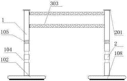
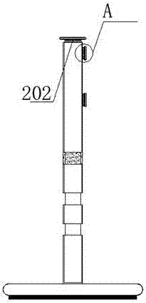
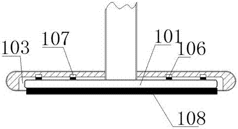
[0018] refer to figure 1 , figure 2 , image 3 , Figure 4 and Figure 5 The shown guardrail device for electric power construction includes a support rod 1 and a first support rod 2, and a support plate 101 is provided at the bottom of the support rod 1 and the first support rod 2, and the support The rod 1 and the first support rod 2 are respectively vertically arranged between the support plate 101, and the support rod 1 and the first support rod 2 are respectively arranged at the middle position of the top surface of the support plate 101, The support rod 1 and the first support rod 2 are respectively welded and fixed to the support plat...


PUM


Abstract

The invention discloses a guard bar device for power construction. The guard bar device comprises a supporting rod and a first supporting rod. Supporting plates are arranged at the bottoms of the supporting rod and the first supporting rod correspondingly, the supporting rod and the first supporting rod are arranged perpendicular to the supporting plates correspondingly and are arranged in the middles of the top surfaces of the supporting plates correspondingly, and the supporting rod and the first supporting rod are fixed to the supporting plates in a welded mode correspondingly; the supporting plates are circular, blocking covers are arranged on outer rings of the supporting rod and the first supporting rod correspondingly, and grooves matched with the supporting plates are formed in the bottom surfaces of the blocking covers correspondingly; and the supporting plates are arranged in the grooves, and three annular grooves are formed in the positions, close to the middles, of the outer rings of the supporting rod and the first supporting rod correspondingly. The guard bar device for power construction is simple in structure, low in cost and suitable for use and popularization.

Description

technical field [0001] The invention relates to a guardrail device for electric power construction. Background technique [0002] The use of electric energy has penetrated into all areas of the national economy and people's lives, and has become the main power form of industry, agriculture, transportation and national defense and an indispensable energy source in people's family life. etc. have been widely used. As a product, electricity is different from other types of products in that it cannot be stored. [0003] Therefore, the power system composed of power plants, transmission lines, substations and distribution networks must produce and transmit electric energy every moment, which must be consistent with the consumption of electric energy by users, which makes electric power production and the national economy , People’s lives are closely related, even a short-term power outage will bring great harm, and a large-scale power outage will cause huge losses to the nation...

Claims


Application Information

Patent Timeline
IPC IPC(8): E04H17/14E04H17/22
CPCE04H17/1413E04H17/22
Inventor 唐星宁
Owner 广州迪然安全检测技术有限公司
Why Eureka
Try Eureka