Stimulation devices and methods for treating dry eye
A dry eye syndrome and stimulator technology, applied in the field of devices for treating dry eye syndrome or eye fatigue, can solve problems such as providing adequate treatment for no symptoms
- Summary
- Abstract
- Description
- Claims
- Application Information
AI Technical Summary
Problems solved by technology
Method used
Image
Examples
Embodiment 1
[0188] Example 1: Stimulation using lacrimal implants
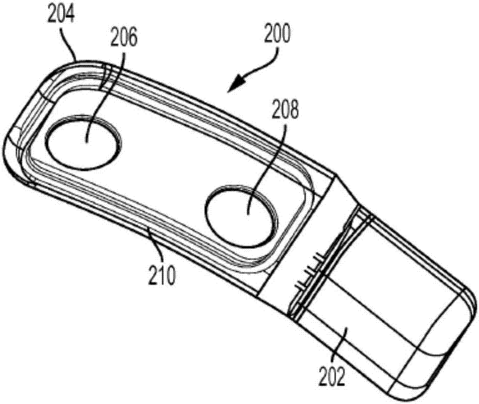
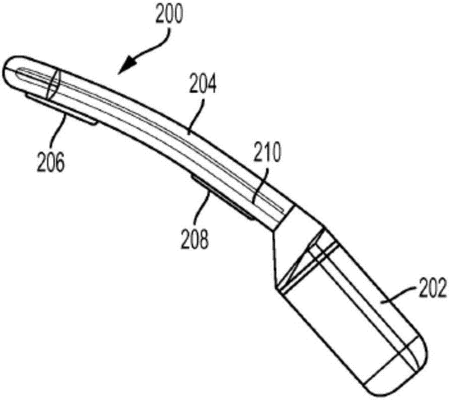
[0189] Patients with a microstimulator implanted in the ocular region were stimulated with 30 Hz non-patterned (control) and on / off patterns (1 s on / 1 s off, 2 s on / 2 sec off, and 5 sec on / 5 sec off) for testing. The implanted microstimulator has Figures 2A-2C features shown in and described herein.
[0190] Patient perception of stimuli differed between the 30 Hz non-patterned waveform control and the time-patterned waveform. Specifically, 3 patients who received the unpatterned waveform at 30 Hz felt their perception of the waveform fade out during the stimulation period, whereas when receiving the time-patterned waveform, no patient reported the perception of the waveform faded out during the stimulation period . When the stimulus was a 30 Hz, 1 s on / off waveform ("pattern 1"), 3 patients perceived the waveform as continuous and 15 patients perceived the waveform as intermittent. When the stimulus was a 30 Hz, 5 ...
Embodiment 2
[0195] Example 2: Stimulation using lacrimal implants (2)
[0196] Use of time-patterned waveforms compared to basal tearing (control 1 = no electrical stimulation) and to 30 Hz stimulation (non-patterned) (control 2) in patients with microstimulators implanted in the ocular region Compared to increased lacrimation as measured by the Schirmer test. The implanted microstimulator has Figures 2A-2C features shown in and described herein. Data are presented below in Table 2 and compare mean tearing results from basal tearing (left, no stimulation) with 30 Hz non-patterned waveform stimulation (middle) and time-patterned patient-optimized stimulation waveform (right) The bar graph for Figure 15 middle. Based on the data in Table 2, the mean value for basal tearing was 4.71 mm, the mean value for non-patterned stimulation at 30 Hz was 4.96 mm, and the mean value was 8.29 mm when temporally patterned stimulation was used. Overall, mean Schirmer scores were increased by about 5...
Embodiment 3
[0201] Example 3: Stimulation using lacrimal implants (3)
[0202] Nineteen patients had microstimulators implanted in the eye region. (Twelve of these patients were the same as in Example 2) For each patient, the patient-optimized time-patterned waveform was determined by adjusting the waveform frequency, pulse width, and on / off period, while collecting patient feedback in order to maximize Reported paresthesias in the orbital region, as described above.
[0203] Use the same controller / energizer for each patient to deliver each waveform. The waveforms tested for each patient included:
[0204] -30Hz
[0205] -30Hz, 1 second on, 1 second off
[0206] -30Hz, 5 seconds on, 5 seconds off
[0207] -70Hz, 1 second on, 1 second off
[0208] -30Hz, pulse width modulated from 100% to 0%, and modulated back to 100% within 1 second
[0209] -30Hz, pulse width modulated from 100% to 70%, and modulated back to 100% within 1 second
[0210] -70Hz, pulse width modulated from 100% t...
PUM
 Abstract
Description
Claims
Application Information
 - R&D
- Intellectual Property
- Life Sciences
- Materials
- Tech Scout
- Unparalleled Data Quality
- Higher Quality Content
- 60% Fewer Hallucinations
Browse by: Latest US Patents, China's latest patents, Technical Efficacy Thesaurus, Application Domain, Technology Topic, Popular Technical Reports.
© 2025 PatSnap. All rights reserved.Legal|Privacy policy|Modern Slavery Act Transparency Statement|Sitemap|About US| Contact US: help@patsnap.com


