Head-borne viewing system comprising crossed optics

A technology of observation system and optical system, applied in the direction of optical components, optics, instruments, etc., can solve problems such as problems

Inactive Publication Date: 2017-08-29
THALES SA
View PDF12 Cites 3 Cited by
  • Summary
  • Abstract
  • Description
  • Claims
  • Application Information

AI Technical Summary

Problems solved by technology

Also, said solution is originally monocular and converting it to a binocular version is problematic

Method used


Image

  • Head-borne viewing system comprising crossed optics
  • Head-borne viewing system comprising crossed optics
  • Head-borne viewing system comprising crossed optics

Examples


Embodiment Construction

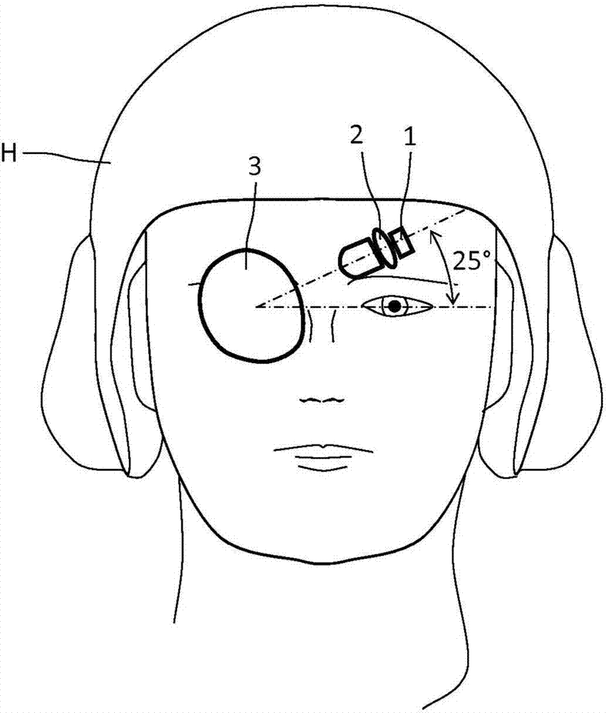
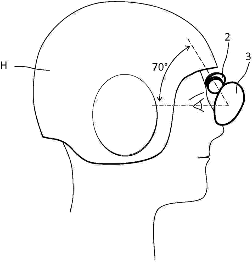
[0032] The viewing system according to the invention is intended to be worn on the user's head. The mechanical support of the head-mounted viewing system can be a helmet, glasses or any other head-mounted support.

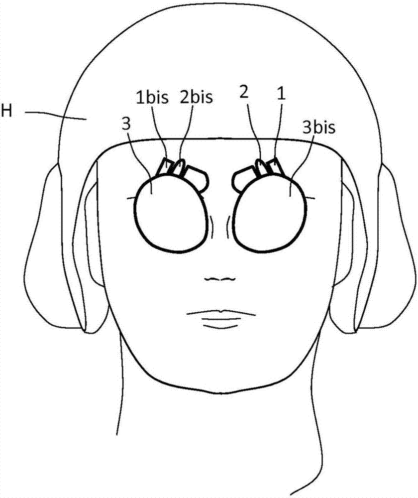
[0033] This viewing system is available in monocular and binocular versions. Each monocular unit includes:

[0034] - display, and

[0035] - Optical components comprising: refractive relay optics, partially transparent and typically translucent light mixers or light combiners integrated into screens, helmet visors or glasses operating by reflection. The light combiner is a thin plate with substantially mutually parallel curved faces which causes little or no distortion of the exterior view. The combiner has no optical power in transmission.

[0036] In the following description, a virtual axis corresponding to a ray passing through the central field of view at the center of the pupil is referred to as an optical axis.

[0037] The monocular unit operates in t...


PUM


Abstract

Monocular or binocular viewing system including a first display (1) and a first optical assembly including a first optical relay (2) and a partially transparent first optical mixer (3), said first optical relay (2) including a first forehead lens, said first optical assembly forming a second image at infinity of a first image displayed by the first display (1), the viewing system being intended to be worn on the head of a user, the first optical mixer (3) being placed in front of one of the two eyes of the user, the exit optical pupil of the first optical assembly being placed level with said eye, the optical axis of the first optical assembly corresponding to the light ray of the central field of view passing through the centre of the exit optical pupil, the first optical mixer (3) being a thin plate having substantially parallel curved faces, each face being defined by a polynomial relationship or a file of points defining a free-form. In the system according to the invention, the optics are said to be crossed, i.e. in the case of a binocular system, if an optical mixer is placed in front of the right eye of the user, the optical relay and the corresponding display are placed in a forehead position above the left eye of the user and under the optical mixer located on the left side. This arrangement is obtained by judiciously choosing the geometric parameters of the various optical elements, their curvatures and the shape of their surfaces: - the inclination of the first optical mixer to the optical axis is about 35 degrees; - the distance separating the exit pupil from the point of intersection of the optical axis and the first optical mixer is about 60 millimetres; and - the inclination of the mean optical axis between the first optical mixer and the first forehead lens in a vertical plane and relative to a straight line joining the centres of the two eyes is about 25 degrees, so that the first optical relay is located level with the forehead, and above the other eye, of the user, position crossed with the first optical mixer.

Description

technical field [0001] The field of the invention is helmet-mounted viewing systems. The system is also known as the "HMD see-through system," an acronym for "head-mounted display." It is used in various applications. For example, it may be worn by aircraft pilots or infantry soldiers. Background technique [0002] The system is used to project a projected image to the user's eyes aimed at infinity and superimposed on the external landscape. The projected image may include symbols representing task information, tasks to be completed or the external environment and / or even images sent by the camera. The camera may be a low-light camera, an infrared camera or a thermal imaging camera. [0003] The system can be monocular or binocular, depending on whether the user perceives the image with one or both eyes. [0004] The systems typically include a small high-resolution display that displays the image to be projected, relay optics, and a light combiner or "mixer" that ensur...

Claims


Application Information

Patent Timeline
Patent Type & Authority Applications(China)
IPC IPC(8): G02B27/01
CPCG02B27/0172G02B2027/0132
Inventor J-L·埃斯皮F·迪亚
Owner THALES SA
Why Eureka
Try Eureka