
A Robot Collision Detection Method Based on SCS Surrounding Structure

A collision detection and robot technology, applied in the field of robotics, can solve the problems of slow calculation speed and low detection accuracy, and achieve the effect of fast collision detection speed, high detection accuracy, and improved detection accuracy.

Active Publication Date: 2019-07-02
中国科学院沈阳计算技术研究所有限公司
View PDF3 Cites 0 Cited by
  • Summary
  • Abstract
  • Description
  • Claims
  • Application Information

AI Technical Summary

Problems solved by technology

[0005] In order to overcome the disadvantages of slow calculation speed and low detection accuracy of the existing enclosure collision detection algorithm for robots, this invention provides a robot collision detection method based on the SCS enclosure structure. According to the structural characteristics of the robot, the collision detection efficiency can be greatly improved. At the same time, to a certain extent, the safety and collision detection accuracy in the working process of the robot are improved.

Method used


Image

  • A Robot Collision Detection Method Based on SCS Surrounding Structure
  • A Robot Collision Detection Method Based on SCS Surrounding Structure
  • A Robot Collision Detection Method Based on SCS Surrounding Structure

Examples


Embodiment Construction

[0033] The following describes the present invention in further detail with reference to the accompanying drawings and embodiments. The flow of the robot collision detection method based on the SCS enclosing structure is as follows: Figure 4 Shown.

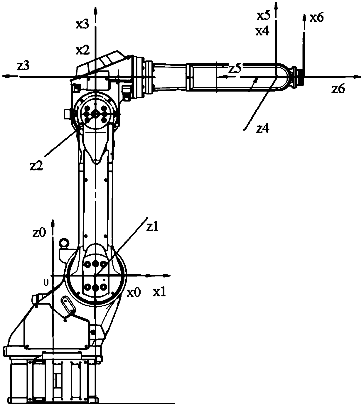
[0034] 1. In the initial stage, take MOTOMAN-MH6 robot as the object, such as figure 2 As shown, the robot rod coordinate system established by the DH method, in which the three coordinate axis directions of the coordinate system {0} are consistent with the corresponding X, Y, and Z coordinate axis directions in the world coordinate system, and the coordinate system {i-1} The change matrix to the coordinate system {i} is:

[0035]

[0036] among them, They are the posture matrix and position matrix of the coordinate system {i} relative to the coordinate system {i-1}; θ i Is the rotation angle of joint i; β i Is the torsion angle between joint i and i+1; α i Is the length of joint i+1; d i Is the offset of joint i.

[0037] 2. Sphere-...


PUM


Abstract

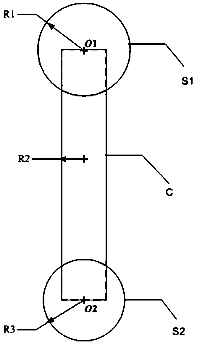
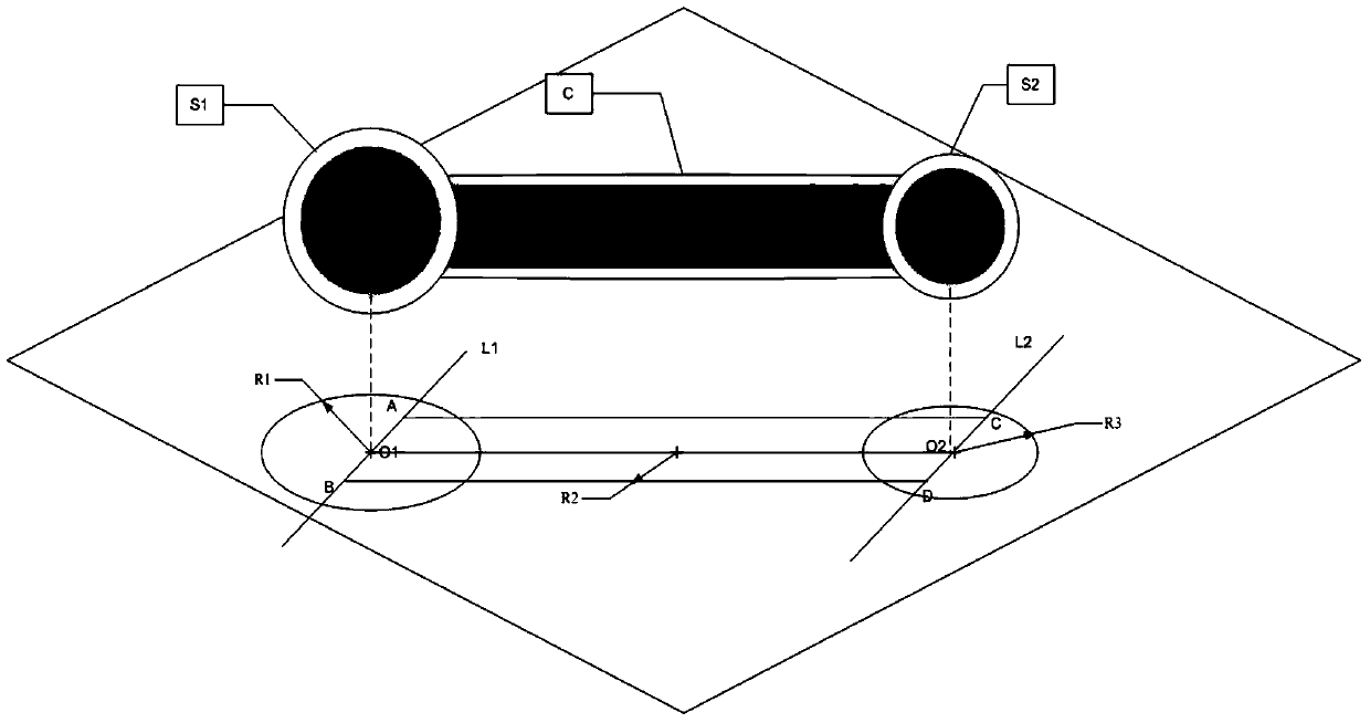
The invention relates to a robot collision detection method based on SCS surrounding structures. A D-H method is adopted for establishing coordinate systems of all rods of a rotor; SCS surrounding structures are adopted for surrounding the connecting rods and joints of the robot, wherein each SCS surrounding structure includes two ball bodies and one cylinder; coordinates of two ball cores of each SCS surrounding structure of the robot are solved; a roller workpiece model and the SCS surrounding structures are projected to an XY plane, a YZ plane and an XZ plane in a world coordinate system, and whether the projection of the roller workpiece model and the projections of the SCS surrounding structures are intersected on the three planes or not is judged; if the projection of the roller workpiece model and the projections of the SCS surrounding structures are intersected on the three planes, the path of the robot is re-planned; if the projection of the roller workpiece model and the projections of the SCS surrounding structures are not intersected on the three planes, whether the end point of the path is reached is judged; if the end point of the path is reached, it is shown that no collision is detected; and if the end point of the path is not reached, the state of the robot is updated. By means of the robot collision detection method based on the SCS surrounding structures, the connecting rods and the joints of the robot can be surrounded compactly, the robot collision detection method is popularly suitable for pillar-shaped structures which continuously rotate in a non-directional manner in three-dimensional space, the collision detection speed of the robot is increased, and the work precision and efficiency of the robot are improved.

Description

Technical field [0001] The invention belongs to the technical field of robots, and specifically is a robot collision detection method based on an SCS (Sphere-Cylinder-Sphere, sphere-cylinder-sphere) surrounding structure. Background technique [0002] Robot technology is one of the important foundations for the realization of advanced manufacturing technology, and it is constantly developing in the direction of high precision, high efficiency and high coordination. The multi-degree-of-freedom robot in robotics is a type of industrial robot. In order to improve the safety of the robot movement, it is necessary to design the corresponding collision detection to avoid the collision between the robot and the workpiece, so that the robot can reach the given position safely, quickly and accurately under various operating conditions. [0003] Early collision detection is mostly based on grid or BSP tree. The grid-based collision detection is simple to implement but not accurate enough, ...

Claims


Application Information

Patent Timeline
Patent Type & Authority Patents(China)
IPC IPC(8): B25J9/04B25J9/16
CPCB25J9/046B25J9/1605B25J9/1666
Inventor 孙维堂刘荫忠王光道
Owner 中国科学院沈阳计算技术研究所有限公司
Learn More