A robot collision detection method, device, electronic equipment and storage medium
A collision detection and robot technology, applied in the computer field, can solve the problems of high controller requirements, difficult to guarantee accuracy, and large amount of calculation.
- Summary
- Abstract
- Description
- Claims
- Application Information
AI Technical Summary
Problems solved by technology
Method used
Image
Examples
Embodiment 1
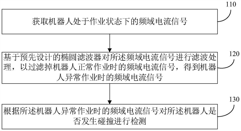
[0048] figure 1 It is a schematic flow chart of a robot collision detection method provided in Embodiment 1 of the present disclosure, and the method is applicable to the scenario of timely detection of whether a robot collides during operation. The method can be executed by a robot collision detection device, and the device can be implemented in the form of software and / or hardware.
[0049] Such as figure 1 As described, the robot collision detection method provided in this embodiment includes the following steps:
[0050] Step 110, acquiring a frequency-domain current signal when the robot is in a working state.
[0051] It can be understood that the mechanical arm of the robot performs the set action under the drive of the motor. Exemplarily, the acquisition of the frequency domain current signal of the robot in the working state includes:
[0052] According to the set sampling period, the time-domain current signal of the robot in the working state is collected from t...
Embodiment 2
[0076] Figure 4 A robot collision detection device provided in Embodiment 2 of the present disclosure includes: an acquisition module 410 , a filter module 420 and a detection module 430 .
[0077] Among them, the acquisition module 410 is used to acquire the frequency-domain current signal when the robot is in the working state; the filter module 420 is used to filter the frequency-domain current signal based on a pre-designed elliptic filter to filter out the normal operation of the robot. The frequency-domain current signal during abnormal operation of the robot is used to obtain the frequency-domain current signal during abnormal operation of the robot; the detection module 430 is used to detect whether the robot collides according to the frequency-domain current signal during abnormal operation of the robot.
[0078] On the basis of the above technical solution, the acquisition module 410 includes:
[0079] The acquisition unit is used to collect the time-domain current...
Embodiment 3
[0098] Refer below Figure 5 , which shows an electronic device suitable for implementing embodiments of the present disclosure (such as Figure 5 A schematic structural diagram of a terminal device or server) 400 in FIG. The terminal equipment in the embodiment of the present disclosure may include but not limited to such as mobile phone, notebook computer, digital broadcast receiver, PDA (personal digital assistant), PAD (tablet computer), PMP (portable multimedia player), vehicle terminal (such as mobile terminals such as car navigation terminals) and fixed terminals such as digital TVs, desktop computers and the like. Figure 5 The illustrated electronic device is only an example, and should not impose any limitation on the functions and scope of use of the embodiments of the present disclosure.
[0099] Such as Figure 5 As shown, the electronic device 400 may include a processing device (such as a central processing unit, a graphics processing unit, etc.) 401, which m...
PUM
 Abstract
Description
Claims
Application Information
 - R&D
- Intellectual Property
- Life Sciences
- Materials
- Tech Scout
- Unparalleled Data Quality
- Higher Quality Content
- 60% Fewer Hallucinations
Browse by: Latest US Patents, China's latest patents, Technical Efficacy Thesaurus, Application Domain, Technology Topic, Popular Technical Reports.
© 2025 PatSnap. All rights reserved.Legal|Privacy policy|Modern Slavery Act Transparency Statement|Sitemap|About US| Contact US: help@patsnap.com


